
VNH3SP30 Motor Driver Carrier MD01B
Retired Product
Search for an alternativeOverview
 |
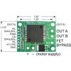
| Pololu High-Current Motor Driver Carrier pinouts and dimensions. |
|---|

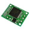
This module is a compact breakout board for ST’s high-power VNH2SP30 or VNH3SP30 motor driver IC, each of which is a fully integrated H-bridge that can be used for bidirectional speed control of a single brushed DC motor. The basic operation of the driver is summarized below, but Pololu also recommend careful reading of the VNH2SP30 datasheet (283k pdf) or VNH3SP30 datasheet (228k pdf) before using this product. The board incorporates most of the components of the typical application diagram on page 8 of the VNH2SP30 datasheet, including pull-up and current-limiting resistors and a FET for reverse battery protection. It ships fully populated with its SMD components, including the VNH2SP30 or VNHSP30 motor driver IC, as shown in the product picture. (Note that the current sense circuit might not be populated on the VNH3SP30 version of the board since only the VNH2SP30 supports current sense.)
Note: Only the VNH2SP30 and VNH5019 support current sense; the current sense circuit might not be populated on the VNH3SP30 version of the board. For more information on the differences between the motor driver versions, see the comparison table below.
In a typical application, the motor power supply is connected at the bottom of the board, the motor on the right side of the board, and the control connections to the left side of the board. The diagnostic/enable pins are pulled high on the board and can be left disconnected if you do not want to monitor the fault conditions of the motor driver chip. INA and INB control the direction of the motor, and the PWM pin turns the motor outputs on or off, allowing you to control motor speed with a supplied pulse width modulation (PWM) signal. The PWM pin is pulled low on the board, so the motor driver outputs are effectively disabled by default; the INA and INB pins are floating (they are not pulled to any particular default voltage). See the truth tables in the VNH2SP30/VNH3SP30 datasheet for more information on how the INA, INB, and PWM pins affect the driver outputs, OUTA and OUTB.
For the VNH2SP30 version, the current sense (CS) pin will output approximately 0.13 volts per amp of output current. If you want to add current sensing to the VNH3SP30 version, or if you want higher-accuracy current sensing with the VNH2SP30 version, please consider Pololu's ±30A ACS714 current sensor carrier.
Note: An 8-pin 0.1″ male header and two 2-pin terminal blocks are included but not soldered onto the boards. You can solder these in yourself and use this board with custom cables or solderless breadboards, or you can solder wires directly to the board for more compact installations.
 |
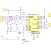
| Schematic of the Pololu High Current Motor Driver Carrier |
|---|
Warning: The top two mounting holes on this carrier board are electrically connected to the OUTA node in an effort to increase thermal dissipation. Please be aware of this if you are mounting more than one of these carrier boards to a metal structure using metal fasteners, or if you are mounting one of these carrier boards to a grounded structure using metal fasteners, as this could cause you to unintentionally short out your power supply. You can avoid the problem in such situations by avoiding those mounting holes or by using non-conducting mounting hardware, such as nylon screws.
Please note that Pololu offer several other products based on these same chips, including dual carrier boards for driving two motors, the qik 2s12v10 dual serial motor controller, the TReX motor controller, the jrk 12v12 USB motor controller with feedback, and the Orangutan X2 robot controller. We also have a family of higher-power motor drivers and simple motor controllers that can deliver more current over a wider operating voltage range.
VNH3SP30, VNH2SP30, and VNH5019 Comparison
 |
| Thermal image of the underside of the VNH5019 motor driver carrier during one of Pololu's current tests. |
|---|
In addition to the VNH2SP30 and VNHSP30, Pololu offer a carrier board for a similar, newer motor driver from ST: the VNH5019. The VNH5019 is the only one of the three with a practical operating voltage above 16 V, and it is the only one that works with 3 V logic.
The current-related values in the table below (i.e. the entries to which footnote 3 applies) are the results of tests on only one or two of each driver version, so they do not capture potential unit-to-unit variation. As such, the values should be treated as rough estimates of performance, not as performance guarantees. While these tests seem to indicate that the VNH2SP30 runs a bit cooler—and hence can deliver more continuous current—than the VNH5019, it is important to note that the three driver versions were tested at different times under potentially different conditions, so the results are not necessarily accurate indications of relative performance.
In Pololu's tests, Pololu noticed that the thermal protection on the VNH5019 was activating at a lower temperature (153°C) than on the VNH2SP30 (170°C), which could partially account for the shorter VNH5019 overheating times. However, Pololu also observed that the VNH5019 was reaching slightly higher temperatures than the VNH2SP30 when used under the same conditions: the VNH5019 reached a temperature of 85°C after 3 minutes at 10 A while the VNH2SP30 reached a temperature of 80°C.
The following table offers a comparison of the three drivers:
| VNH3SP30 | VNH2SP30 | VNH5019 | |
|---|---|---|---|
| Operating voltage: (1) | 5.5 – 16 V (2) | 5.5 – 16 V | 5.5 – 24 V |
| MOSFET on-resistance (per leg): | 34 mΩ typ. | 19 mΩ max. | 18 mΩ typ. |
| Max PWM frequency | 10 kHz | 20 kHz | 20 kHz |
| Current sense | n/a | 0.13 V/A | 0.21 V/A |
| Over-voltage shutoff | 36 V min. (2) / 43 V typ. | 16 V min. / 19 V typ. | 24 V min. / 27 V typ. |
| Logic input high threshold | 3.25 V min. | 3.25 V min. | 2.1 V min. |
| Time to overheat at 20 A (3) | 8 s | 35 s | 20 s |
| Time to overheat at 15 A (3) | 30 s | 150 s | 90 s |
| Current for infinite run time (3) | 9 A | 14 A | 12 A |
1 The VNH3SP30 can survive input voltages up to 40 V, and the VNH2SP30 and VNH5019 can survive input voltages up to 41 V, but the over-voltage shutoff will kick in at lower voltages.
2 While VNH3SP30’s over-voltage shutoff doesn’t activate until 36 V, in Pololu's experience, shoot-through currents make PWM operation impractical above 16 V.
3 Typical results using the Pololu motor driver carrier boards with 100% duty cycle at room temperature (with no forced airflow or heat sinking beyond the carrier PCB).
Real-world power dissipation considerations
The motor drivers have maximum current ratings of 30 A continuous. However, the chips by themselves will overheat at lower currents (see table above for typical values). The actual current you can deliver will depend on how well you can keep the motor driver cool. The carrier printed circuit board is designed to draw heat out of the motor driver chips, but performance can be improved by adding a heat sink. In Pololu's tests, Pololu were able to deliver short durations (on the order of milliseconds) of 30 A and several seconds of 20 A without overheating. At 6 A, the chip gets just barely noticeably warm to the touch. For high-current installations, the motor and power supply wires should also be soldered directly instead of going through the supplied terminal blocks, which are rated for up to 15 A.
This product can get hot enough to burn you long before the chip overheats. Take care when handling this product and other components connected to it.
Many motor controllers or speed controllers can have peak current ratings that are substantially higher than the continuous current rating; this is not the case with these motor drivers, which have a 30 A continuous rating and over-current protection that can kick in as low as 30 A (45 A typical). Therefore, the stall current of your motor should not be more than 30 A. (Even if you expect to run at a much lower average current, the motor can still draw short bursts of high currents, such as when it is starting, if special steps are not taken.)
Reverse-battery protection
The motor driver boards include an N-channel MOSFET for reverse-battery protection. This component keeps the motor driver from destroying itself if the input power is accidentally connected backwards. However, this component does slightly increase the total resistance between your battery and your motor. For slightly improved performance, the MOSFET can be bypassed by connecting the negative battery terminal to the bypass pin. (This terminal will also need to be connected to your logic supply ground.)
Exact shipping can be calculated on the view cart page (no login required).
Products that weigh more than 0.5 KG may cost more than what's shown (for example, test equipment, machines, >500mL liquids, etc).
We deliver Australia-wide with these options (depends on the final destination - you can get a quote on the view cart page):
- $3+ for Stamped Mail (typically 10+ business days, not tracked, only available on selected small items)
- $7+ for Standard Post (typically 6+ business days, tracked)
- $11+ for Express Post (typically 2+ business days, tracked)
- Pickup - Free! Only available to customers who live in the Newcastle region (must order online and only pickup after we email to notify you the order is ready). Orders placed after 2PM may not be ready until the following business day.
Non-metro addresses in WA, NT, SA & TAS can take 2+ days in addition to the above information.
Some batteries (such as LiPo) can't be shipped by Air. During checkout, Express Post and International Methods will not be an option if you have that type of battery in your shopping cart.
International Orders - the following rates are for New Zealand and will vary for other countries:
- $12+ for Pack and Track (3+ days, tracked)
- $16+ for Express International (2-5 days, tracked)
If you order lots of gear, the postage amount will increase based on the weight of your order.
Our physical address (here's a PDF which includes other key business details):
40 Aruma Place
Cardiff
NSW, 2285
Australia
Take a look at our customer service page if you have other questions such as "do we do purchase orders" (yes!) or "are prices GST inclusive" (yes they are!). We're here to help - get in touch with us to talk shop.
Have a product question? We're here to help!
Guides

The Maker Revolution
Projects

The Rats Nest VCC Desktop Power Supply

Remote-Controlled Mars Rover

FlipperMate: Hands-Free Pinball

Makers love reviews as much as you do, please follow this link to review the products you have purchased.
Product Comments