

QTR-1RC Reflectance Sensor (2-Pack)
Retired Product
Search for an alternativeNote: The QTR-1RC reflectance sensor requires a digital I/O line to take readings. The similar QTR-1A reflectance sensor is available with an analog output.
Functional description
 |
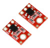
The Pololu QTR-1RC reflectance sensor carries a single infrared (IR) LED and phototransistor pair. To use the sensor, you must first charge the output node by applying a voltage to the OUT pin. You can then read the reflectance by withdrawing that externally applied voltage on the OUT pin and timing how long it takes the output voltage to decay due to the integrated phototransistor. Shorter decay time is an indication of greater reflection. This measurement approach has several advantages, especially when multiple units are used:
- No analog-to-digital converter (ADC) is required
- Improved sensitivity over voltage-divider analog output
- Parallel reading of multiple sensors is possible with most microcontrollers
The LED current-limiting resistor is set to deliver approximately 17 mA to the LED when VIN is 5 V. The current requirement can be met by some microcontroller I/O lines, allowing the sensor to be powered up and down through an I/O line to conserve power.
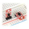
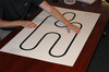
This sensor was designed to be used with the board parallel to the surface being sensed. Because of its small size, multiple units can easily be arranged to fit various applications such as line sensing and proximity/edge detection.
For a line sensor with eight of these units arranged in a row, please see the QTR-8RC reflectance sensor array; for a similar array of three slightly different sensor components, see the QTR-3RC. For a similar, smaller sensor with longer range, and intended for use with the board perpendicular to the surface, please see the QTR-L-1RC reflectance sensor.
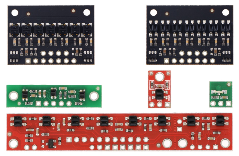 |
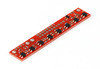
QTR sensor size comparison. Top row: QTRX-HD-07, QTR-HD-07; middle row: QTR-3, QTR-1, QTR-L-1; bottom row: QTR-8. |
|---|
Specifications
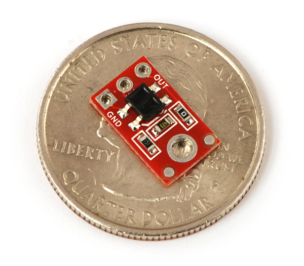
- Dimensions: 0.3" x 0.5" x 0.1" (without optional header pins installed)
- Operating voltage: 5.0 V
- Supply current: 17 mA
- Output format: digital I/O-compatible signal that can be read as a timed high pulse
- Optimal sensing distance: 0.125" (3 mm)
- Maximum recommended sensing distance: 0.375" (9.5 mm)
- Weight without header pins: 0.008 oz (0.2 g)
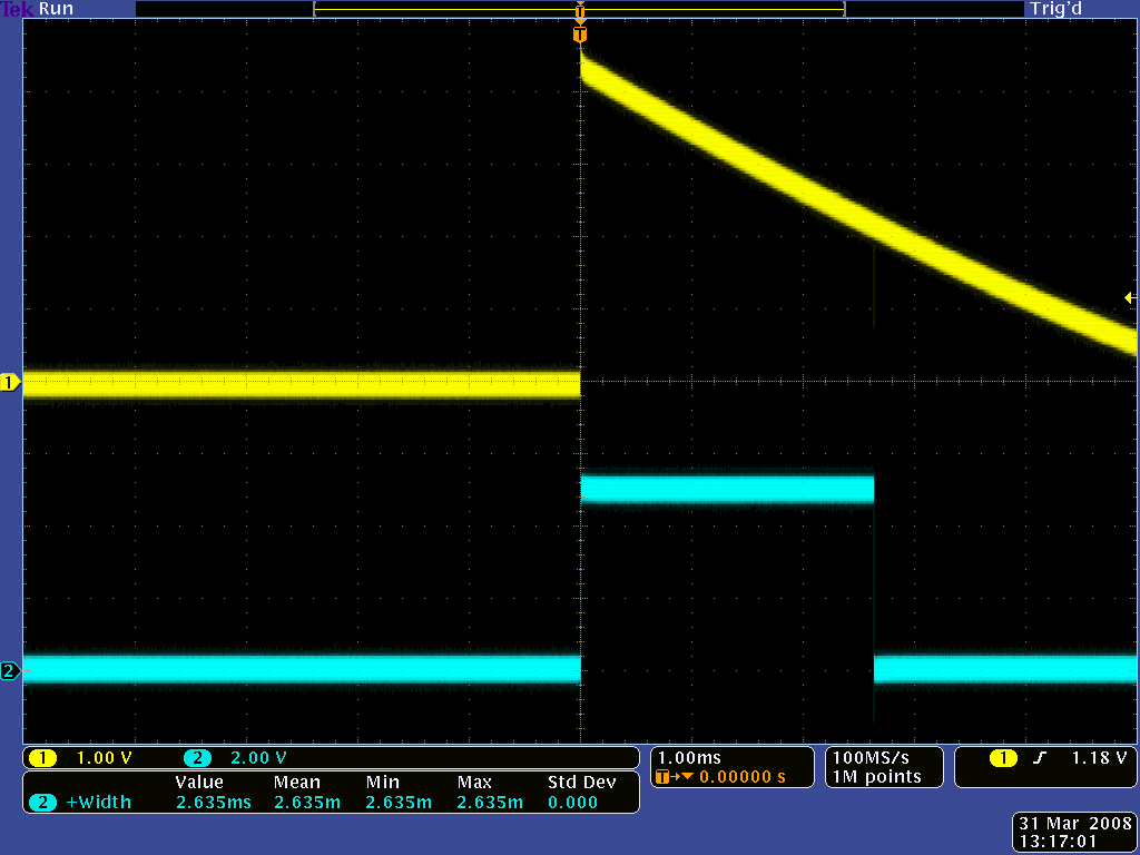 |
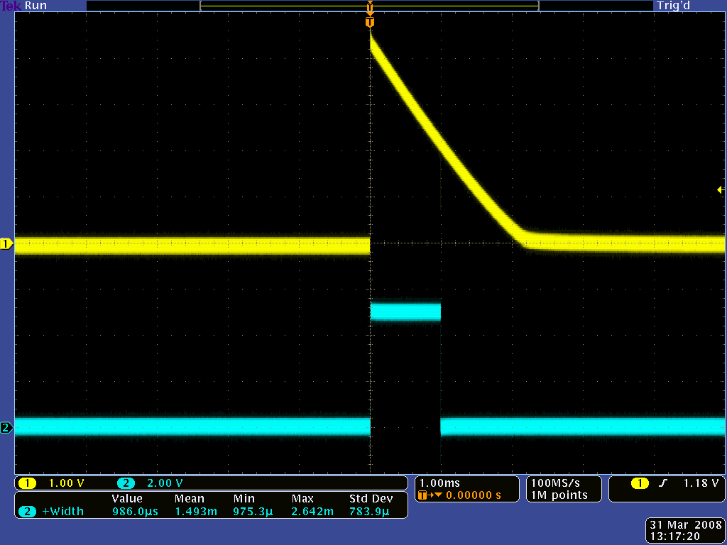
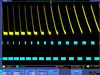
QTR-1RC output (yellow) when 1/8" above a black line and microcontroller timing of that output (blue). |
|---|
Interfacing the QTR-1RC output to a digital I/O line
Like the Parallax QTI, this sensor requires a digital I/O line capable of driving the output line high and then measuring the time for the output voltage to decay. The typical sequence for reading a sensor is:
- Set the I/O line to an output and drive it high.
- Allow at least 10 µs for the sensor output to rise.
- Make the I/O line an input (high impedance).
- Measure the time for the voltage to decay by waiting for the I/O line to go low.
 |
These steps can typically be executed in parallel on multiple I/O lines.
With a strong reflectance, the decay time can be as low as several dozen microseconds; with no reflectance, the decay time can be up to a few milliseconds. The exact time of the decay depends on your microcontroller’s I/O line characteristics. Meaningful results can be available within 1 ms in typical cases (i.e. when not trying to measure subtle differences in low-reflectance scenarios), allowing up to 1 kHz sampling.
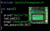
Pololu's Pololu AVR library provides functions that make it easy to use these sensors with Pololu's Orangutan robot controllers; please see the QTR Reflectance Sensors section of Pololu's library command reference for more information. Pololu also have a Arduino library for these sensors.
Included components
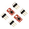
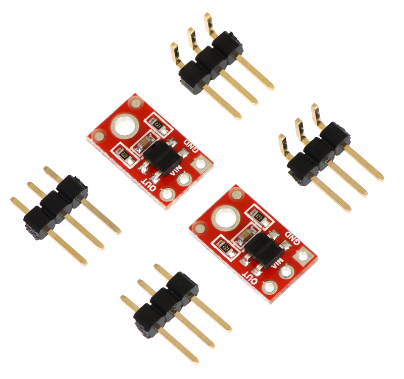
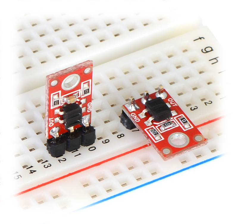
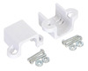
This module has a single mounting hole intended for a #2 screw (not included); if this mounting hole is not needed, this portion of the PCB can be ground off to make the unit even smaller. Each pack of two reflectance sensors includes sets of straight male header strips and right-angle male header strips, which allow you to mount them in the orientation of your choice (note: the header pins might ship as 1×6 strips that you can break into two 1×3 pieces). You can also solder wires, such as ribbon cable, directly to the pads for the most compact installation.
|
|
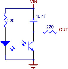
How it works in detail
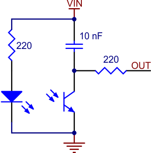
With only four components (or five, if you count the coupled IR LED and phototransistor separately), the operation of this sensor is relatively basic. The emitter side is just an IR LED with an appropriate current-limiting resistor. The light from the emitter leaves the sensor, reflects off a nearby surface, and returns to the detector.
The detector side is a resistor-capacitor (RC) circuit, where the resistance comes from the phototransistor and is a measure of the incident infrared light, and the decay time is proportional to the resistance. The first step of the sensor-reading process—driving the sensor output high—discharges the integrated 10 nF capacitor and puts both sides at the same voltage (VIN). Alternatively, you can think of this as “charging the output node”, and it is functionally equivalent to charging a capacitor with one side connected to ground. Once you are no longer supplying an external voltage to the output pin, the capacitor can slowly charge through the phototransistor, with the rate of charging being a function of the phototransistor’s resistance (which is in turn a function of the incident IR). As the capacitor charges, the voltage on the output side drops, eventually reaching zero when the capacitor is fully charged. Alternatively, you can think of this as “discharging the output node”, and it is functionally equivalent to discharging a capacitor with one side connected to ground.
The 220 O resistor on the OUT line serves to limit the current flow, making it possible for a microcontroller output to safely charge the output node prior to each reading. It has very little effect on the sensor output.
|
|
People often buy this product together with:
 | QTR-8RC Reflectance Sensor Array |
 | Pololu Micro Metal Gearmotor Bracket Extended Pair |
 | QTR-1A Reflectance Sensor (2-Pack) |
Dimensions
| Size: | 0.3" × 0.5" × 0.1"1 |
|---|---|
| Weight: | 0.2 g2 |
Identifying markings
| PCB dev codes: | irs01a |
|---|
Notes:
Documentation and other information
-

Pololu QTR Reflectance Sensor Application Note (Printable PDF)
Information about using the Pololu QTR reflectance sensors, including differences between A-type and RC-type sensors and sample oscilloscope screen captures of sensor outputs.
-
Pololu AVR C/C++ Library User’s Guide (Printable PDF)
Information about installing and using the C/C++ libraries provided for use with Pololu products.
-
Pololu AVR Library Command Reference (Printable PDF)
A reference to commands provided in the Pololu C/C++ and Arduino libraries for the AVR.
-
Building Line Following and Line Maze Courses (Printable PDF)
Step-by-step instructions for building your own line-following courses.

File downloads
-
Datasheet for Fairchild’s QRE1113GR reflective object sensor (202k pdf)
This is the sensor that Pololu initially used in the Pololu QTR reflectance sensors, but Pololu have since switched to a similar generic unit that has slightly longer range.
-
Drill guide for QTR-1x Reflectance Sensor (13k dxf)
This DXF drawing shows the locations of all of the board’s holes.
-
Dimension diagram of the QTR-1x Reflectance Sensor (134k pdf)
-
3D model of the QTR-1RC Reflectance Sensor (2MB step)
-
Guide utilisateur du senseur QTR (suiveur de ligne) (1MB pdf)
Un guide utiliser et exploiter un senseur QTR (détecteur de ligne) (version 0.1). Note: This French translation of Pololu's QTR sensor documentation was made by Pololu's distributor MCHobby.
Recommended links
-
Matthew Phillipps ported Pololu's Arduino Library for the Pololu QTR Reflectance Sensors to the mbed platform. The Arduino library is designed to work with Pololu QTR reflectance sensors, so the mbed library should too, but Matthew points out he only tested it with the analog sensors. This library was not written and is not maintained by Pololu.
-
Arduino library for the Pololu QTR Reflectance Sensors
This library for Arduino makes it easy to interface with Pololu QTR Reflectance Sensors.
Exact shipping can be calculated on the view cart page (no login required).
Products that weigh more than 0.5 KG may cost more than what's shown (for example, test equipment, machines, >500mL liquids, etc).
We deliver Australia-wide with these options (depends on the final destination - you can get a quote on the view cart page):
- $3+ for Stamped Mail (typically 10+ business days, not tracked, only available on selected small items)
- $7+ for Standard Post (typically 6+ business days, tracked)
- $11+ for Express Post (typically 2+ business days, tracked)
- Pickup - Free! Only available to customers who live in the Newcastle region (must order online and only pickup after we email to notify you the order is ready). Orders placed after 2PM may not be ready until the following business day.
Non-metro addresses in WA, NT, SA & TAS can take 2+ days in addition to the above information.
Some batteries (such as LiPo) can't be shipped by Air. During checkout, Express Post and International Methods will not be an option if you have that type of battery in your shopping cart.
International Orders - the following rates are for New Zealand and will vary for other countries:
- $12+ for Pack and Track (3+ days, tracked)
- $16+ for Express International (2-5 days, tracked)
If you order lots of gear, the postage amount will increase based on the weight of your order.
Our physical address (here's a PDF which includes other key business details):
40 Aruma Place
Cardiff
NSW, 2285
Australia
Take a look at our customer service page if you have other questions such as "do we do purchase orders" (yes!) or "are prices GST inclusive" (yes they are!). We're here to help - get in touch with us to talk shop.
Have a product question? We're here to help!
- Pololu Ball Caster with 1/2" Metal BallSKU: POLOLU-953 Brand: PololuThis ball caster uses a 1/2" diameter metal ball. The height of the assembled ki ...
- 120 Pack of Electrolytic Capacitors (12 types, 10 of each)SKU: CE05130 Brand: Core ElectronicsThis pack of Electrolytic Capacitors includes 12 types, 10 of each.
- 3.3V + 5V Solderless Breadboard Power Supply Module AdaptorSKU: CE05111 Brand: Core ElectronicsGet your prototype online faster with a premade power supply module that can be ...
- IIC LCD1602 (Gadgeteer Compatible)SKU: DFR0063 Brand: DFRobot
This is another great LCD display compatible with Gadgeteer modules from DFRo ...


Guides

The Maker Revolution
Projects

The Rats Nest VCC Desktop Power Supply

Remote-Controlled Mars Rover

FlipperMate: Hands-Free Pinball

Makers love reviews as much as you do, please follow this link to review the products you have purchased.
Product Comments