Chances are if you are anything like me, being a maker is often an excuse to create as big of a mess as possible during the duration of a project. And after the project is finished? You are left with an enormous mess to clean up, taking away valuable time to play around with your newly completed project. This soon became a problem, and with any problem, there is always a solution that involves soldering and 3D printing! I decided to build a battery-powered desk vacuum that will be able to collect at least some of my mess for me and let me play around with it at the same time. Basically a win-win.
- A Raspberry Pi Pico takes button inputs and sends appropriate output to the MOSFET.
- A MOSFET supplies power to the necessary motors
- A Lithium battery charger/booster module takes the power from an 18650 lithium
cell and supplies 5v to the components.
- Raspberry Pi Pico
- Mosfet module
- Charger/Booster board
- Diode
- 18650 Battery
- Suction motor: Unfortunately, Core Electronics does not stock this motor type, but I found an AliExpress link for one I salvaged. For future reference, it's an RF-500TB-18280.
- Little brushed motor
- Button
- Slide switch
- I also have this screw, nut and bolt set from Bunnings, that all of the major components are screwed together with.
This project costs about $50 +3D printer filament if all parts are purchased new, the design can be modified for different parts you have on hand as long as you can modify the CAD design (I salvaged and reused a few parts from old electronics).
- Small, compact and comfortable to hold in your hand.
- Rechargeable
- Low noise (60db max)
- Simple, modern and timeless design (fits in on any makers desk)
The brains of the operation will be the ever-helpful $5, Raspberry Pi Pico, running Micropython.
The problem with relying on this little microcontroller to run big motors is that, well, It can’t. So I used a little MOSFET module that can handle way more power (60V @ 20A) to run the motors. Little bit overkill, considering I only need 5 volts, at around 1 amp, but oh well.
To power both the Pi and the Motors, I used a little charger/booster board that I found, and so far it has been awesome and saves loads of space compared to two discrete charging and boosting modules. This module was used in conjunction with a single 18650 cell, which gives about 3-4 hours of continuous vacuuming time (about 2 weeks for my use).
The main suction motor will make use of a pretty fast and high torque, low profile brushed DC motor. This motor allows the vacuum to remain relatively small while also being able to spin the turbine at relatively high speeds.
For the motorized brush, I needed a low profile motor that is relatively slow as to not flick the bits away that I am trying to suck up, so I found a cheap 5 V brushless fan and cut the motor housing and blades off, leaving just the motor hub, where I later 3D printed a little brush that can fit over the hub.
I then combined these parts according to the following circuit diagram.
As seen from the diagram, the MOSFET must be connected to pin 10 on the Pico (and indicated by the below code).
The button is wired up to both ground and pin 13 (pressing the button will pull the pin low)
You may notice that only the center pin of the button was used. This is because the design can later be upgraded to sport an OLED display where the user can change vacuuming profiles. However, this is not necessary for the base design.
If you want to upgrade the design later, the remainder of the switch terminals can be wired up to the pico, as I have done below:
Additionally, the Pico is powered through pin 40, in order to keep the Micro-USB jack free, for access later.
Next, some simple Micropython code was written in order to take a button input and turn on the motor (head over to my Google Drive to download the code)
from machine import Pin, I2C, PWM
import utime
# ^^^ Importing some Libaries.

motor=65025 #Assign Motor Duty Cycle (This is just on 100% of the time)
pwm = PWM(Pin(10)) #Tell Pico that Mosfet is on Pin 10
pwm.freq(100) #Set PWM frequency to 100 Hertz (100 times a second)

centreb = Pin(13, Pin.IN, Pin.PULL_UP) #Assign centre button to pin 13
centre = False #Set variable centre to false

# vvv Defining function interrupt centre to interupt while loop if button is pressed.
def intcentre(pin):
  global centre
  centre = True
  global interrupt_pin
  interrupt_pin = pin

#vvv setting up IRQ trigger if button is pressed
centreb.irq(trigger=Pin.IRQ_RISING, handler=intcentre)
button = False # Assigning button to false
while True:
    if centre: #if button is pressed, centre will = true
        button = not button #Boolean logic: if true false, if false true.
        centre = False
        if button: # if button = true, turn on motor
            pwm.duty_u16(motor)
            print("on")
        if not button: # if button does not = true, turn off motor
            pwm.duty_u16(0)
            print("off")
    utime.sleep(0.5) # waits half a second between inputs to hopefully add some debouncing.
I then used the open-source software - Thonny, to upload the Python code onto the Pi Pico. Numerous tutorials can be found online, however, I liked the one produced by Core Electronics.
Next, I had to design a case and several key components such as the vacuum turbine, and 3D print them. At this point, I had only had my printer for a few weeks, and had never used a parametric modelling system before (Albeit, I had used Blender for about 4 years already, and was very familiar with polygon-based 3D modelling).
It’s important to remember while modelling, the limitations and benefits that come into play when using an additive manufacturing method, such as 3D printing. During the design process, I tried to keep in mind the possible forces that will be in place when using the vacuum and try to identify weak points (i.e. layer lines, screw posts, etc). Additionally, I tried to keep overhangs at a minimum, in order to reduce the use of support material, however, some components still require its use. I chose to use the free personal version of Fusion 360.
The first revision of the vacuum actually looked similar (At least externally) to the final. I had a vision for the final design all along and managed to stick with it to the end. However, it still was not perfect. The clam-shell spit-in-half case weakened it significantly, and there was no practical reason why it could not be one piece, apart from needing support material in order to print it (not a big deal).
By revision 12 I had finally nailed all of the tolerances and created a design I liked, however, the gaping screw holes at the front still were a little ugly, and there was no secondary brush motor.
The vacuum turbines also went through some iterations:
|
|
|
|
|
First design: 9 blades that point straight up. It did not move that much air, and did not create a very strong vacuum |
Second design: still 9 turbines, but I planned to use a bearing to reduce friction. It didn’t go well, created too much noise, and actually increased friction slightly due to rubbing. |
Third design. Reduced blade count to 7, increased height, and added slight pitch. Improved airflow greatly, and was the final turbine design. |
As seen in this view of the underside of the case, these ribs were included in order to strengthen the case from flexing when held from the top. This is a commonly seen feature in mass-produced plastic cases, so I decided to implement it into the design as a method of reducing flex while also not adding too much weight and unnecessary plastic. Additionally, a lip was created around the bottom edge, in order to reduce flex, and support the plastic from two sides.
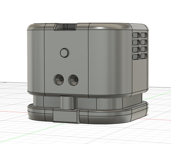
And sometime later, by revision 115 of small adjustments to tolerances, part fitments, and blower configurations (sigh). After a week or two of tinkering, I ended up with a pretty cool looking vacuum design. As seen, I added a cutout for the secondary brush motor, along with removing the screw holes on the front of the case, and created a nice sleek design.
|
|
|
Below is an exploded view diagram of the assembly process of the vacuum I quickly put together in a Blender, alongside the finished render of the design.
3D printing and case preparation:
The entirety of the vacuum case and suction components (turbine, motor mount) are 3D printed, I used my Ender 3 V2 (0.4mm nozzle), and Cura slicer, with all of the components printed in generic PLA filament (you don’t need anything fancy). For Cura settings, I used mainly the default parameters for generic PLA, apart from 3 main settings: Infill, Supports, and quality.
|
Cura Settings: |
||||
|
Part: |
Infill percentage: |
Supports?: |
Support density: |
Quality Profile: |
|
Cover |
70-80% |
Yes |
8-10% |
Dynamic |
|
Base |
60-70% |
Yes |
10-15% |
Dynamic |
|
Dust Collector: |
60-70% |
No |
- |
Dynamic |
|
Motor Mount |
60-70% |
Yes |
10-15% |
Standard-Low |
|
Turbine |
100% |
No |
- |
Dynamic |
|
Brush |
100% |
No |
- |
Super |
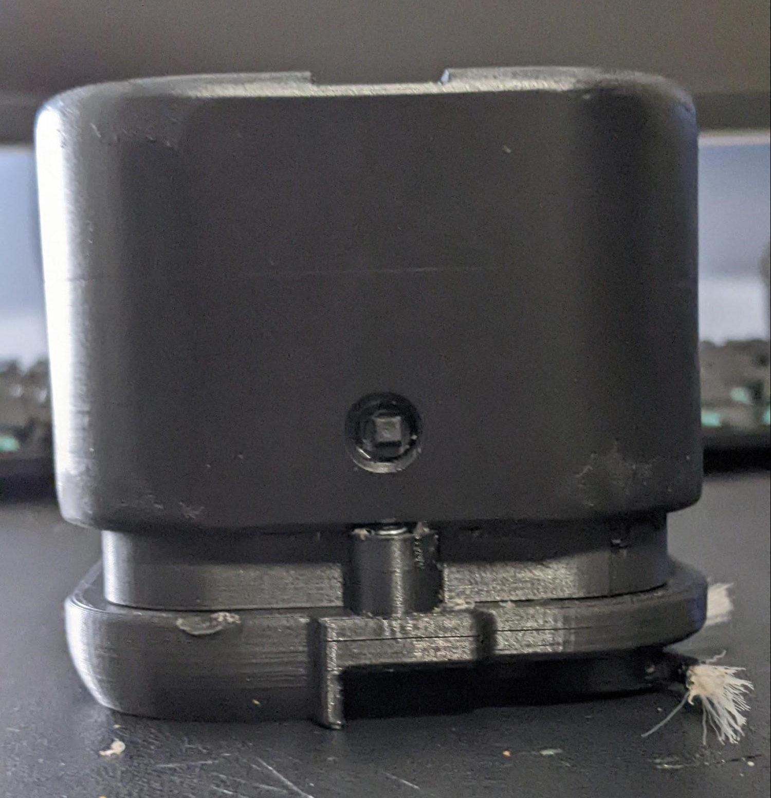
Be aware that every printer is different, and some trial and error is required to get these parts perfect, and tolerances tight. Exhibit A: (And there’s a whole lot more where that came from)!
After these components had finished printing, they required some post-processing. I simply gave most external parts a light sanding, with the case receiving the most treatment, as it was the part the user interacted with the most. For the case, I gave it a few coats of matt clear coat I found at Kmart for $3. The final result looks great, and I will definitely be using this process again.
Now for the part, I like the most: putting everything together. After spending a few hours printing everything off, I began to assemble the vacuum.
Fitting parts in case: I mounted both the pi pico and the MOSFET module on the internal roof of the vacuum cover with hot glue (a trend in the assembly of this device). Placing the Pi Pico on the raised section made on the case roof also allows the USB port to be accessed if you wanted to upload your own code for controlling the device. The placement for the rest of the parts is all accounted for within the design of the vacuum, such as the suction and brush motors.
|
|
|
|
|
Fitting Parts into the Case, through a copious mixture of Screws and Hot Glue. |
Screwing in the switch |
Charge module placed in the top of the case. |
|
|
|
|
|
Motor and battery fit into the motor mount. (I didn’t have diodes on hand, so I used LED’s) |
Dust cover plate going on. |
Brushed base plate. (notice how power is transmitted through the plate screws to the motor) |
Brush motor and transmitting power through the base.
The small brush motor at the base of the vacuum requires special preparation that involves some precise cutting of the brushless fan enclosure in order to obtain just the internal motor hub. I recommend using side cutters to do this, they will allow the greatest precision.
After the motor hub is freed from the frame (and blades are removed to the best of ability), the printed brush piece should fit snugly around the motor hub, ensuring that it can still be removed for replacement in the future. The brush however will still not have bristles, I used an old makeup brush and hot glued them in, due to the compliance of the bristles ensuring the motor will not stall when bristles make contact with a wall or object. The motor can then be glued into base, with wires routed through the holes in the base plate, where they then can be soldered to some washers that will make contact with the bolts when they are threaded through the base plate.
Additionally, extra wires will need to be soldered to the bolts that are placed within the interface plate between the base and motor mount. These wires are then placed in parallel with the suction motor so that both positive and both negatives are connected together (getting wiring backwards will only result in the brush motor not spinning, simply flip the polarity of wires to fix).
The assembly should look similar to this (Note: I replaced the original black and red wires with larger gauge wire in order to fit into the groove better, however original wire will still fit)
|
|
|
|
|
|
|
 |
 |
Overall, I am thrilled with how the project turned out, and has actually been very useful for cleaning up little crumbs and such on my desk. Now it's no 2000 watt beast, but it is plenty to be able to suck up balls of solder, hot glue bits and can even lift a whole piece of paper! And it can do it all quietly (40-50 db!) I love this project and I think it's one of the best things that I have made so far. Obviously, it can be improved, such as a stronger suction motor, independent speed control for the brush, ect. Still, I learned heaps and I hope I can teach others something new as well.
Now that the base design of the Vacuum is finished, I also included some optional upgrades that I have completed (Note: these are just the upgrades that I have done to show what you can do. I have provided the CAD files and code, however, they will both most likely need to be modified in order to work with your parts and modifications).
Convert Charging port from micro USB to USB-C:
I replaced the micro usb charger with a USB-C port, that both charges the battery and can also load firmware onto the Pi Pico. I did this using this USB-C breakout board.

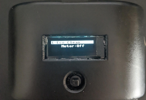
I also included a screen (involving a reprint of the case) that can display current motor status, internal temperature, ect. I made use of this display, only because the PiicoDev one was out of stock :( It's the one I would recommend as it has more pixels, and is better suited for more information.
I placed a thermistor onto the motor and connected it to the ac-dc pin 2 on the pi pico. This is to measure temperature to ensure the motor does not overheat (can only overheat if running for 20ish minutes plus in a hot room).
I also wrote some better code, making use of the screen and the extra button positions (the updated code is also on my Google Drive), which has 4 different cleaning modes. Eco clean, Power Clean, Pulse Clean and Custom Clean, all of which have different motor speeds, with custom clean allowing the user to set a custom motor speed, down to 10% (Note: Requires SSD1306 driver to be downloaded from github).
This is more or an aesthetic change, and can be done on the original vacuum design. I found some “air conditioner foam” lying around, and decided to place it on the internal vents of the design. This does not reduce airflow by a large margin, and helps to hide my ugly internal wiring.


