This guide will help you get started with a PiicoDev® Servo Driver module. We'll take a tour of the module and walk through some examples to drive common servos.
Servo motors are integrated motors that contain their own power circuitry and controller. You just need to provide a stable power supply and a control signal. They're generally available in two flavours:
- Positional (aka. "angular"); these can be set to hold a specific angle and are really useful for creating exact angular movements like opening a gate or as a joint in a robotic arm.
- Continuous Rotation; these behave like a motor with direction and speed control.
Servos have convenient mounting tabs and a splined output shaft that couples to one of the "servo horns" that are often supplied. You can even get special servo wheels! Mount one of these accessories to your servo before starting - it's much easier to see what's going on that way!
Contents:
- Hardware
- Required Hardware
- Connect a Servo to the Servo Driver
- Connect the Servo Driver to your Dev. Board
- Setup Thonny
- Download / Install PiicoDev Modules
- Example: Angular Servo
- Example: Continuous Rotation Servo
- Example: Connecting Multiple Servo Drivers Together
- Conclusion
To get started - select your dev. board below.
Hardware
Required Hardware
To follow along you'll need:
- A Raspberry Pi Pico (with Soldered Headers) or Pico W (with Soldered Headers)
- A PiicoDev Servo Driver
- A PiicoDev Expansion Board for Raspberry Pi Pico
- A PiicoDev Cable
- A power supply with USB-C connector. This could be:
- A complete Power Supply with USB-C connector - I'll use this in this article.
- Portable option: a USB power bank and USB-C cable.
- At least one servo. In this guide I'll use two different models: an FS90 (positional) and FS90R (continuous rotation) servo.
- (Optional) A PiicoDev Platform will keep everything mounted securely.
Connect a Servo to the Servo Driver
Address Switch (ASW)
Each PiicoDev Servo Driver has an Address Switch labelled ASW, ensure both poles of this switch are in the OFF position.
Connect a Servo to Channel 1
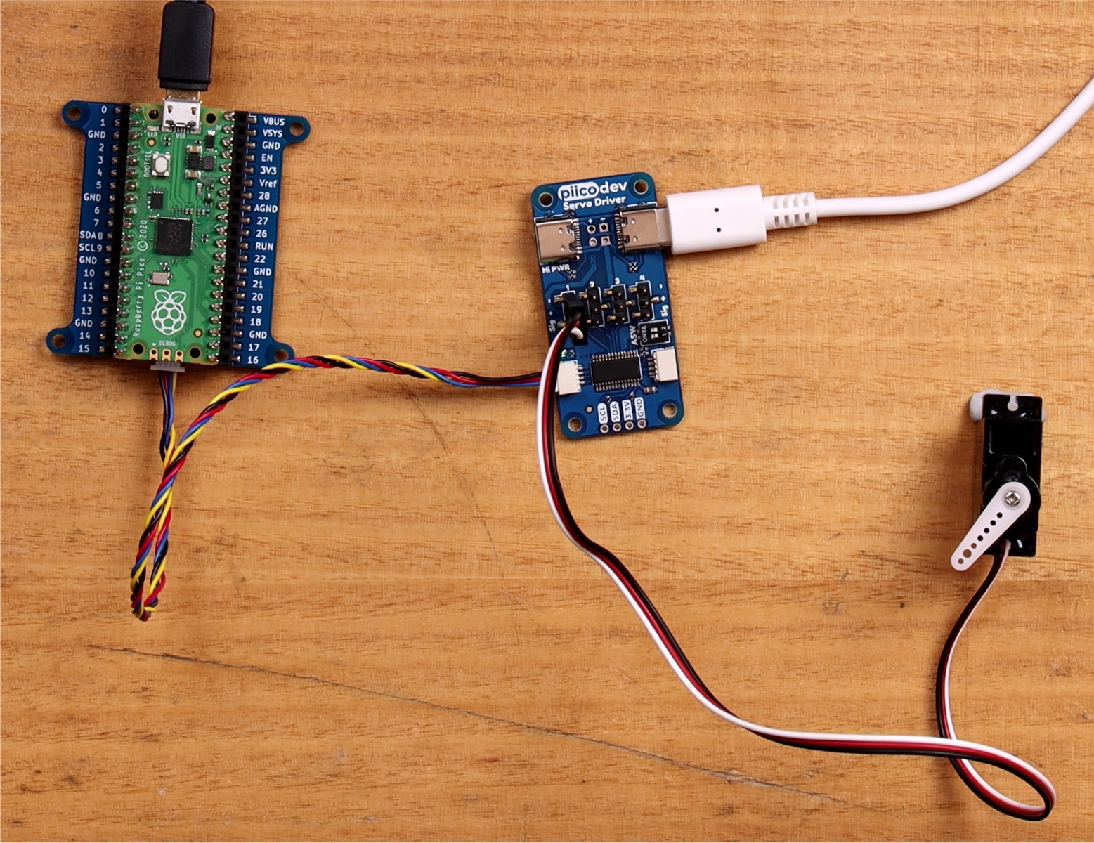
The PiicoDev Servo Driver has four servo control channels labelled 1-4. For now we'll connect a servo to Channel 1. Servos usually come with a standard 3-pin connector with connections for Ground, Power, and Signal. On the Servo Driver these are labelled -, + and sig respectively. Make sure you connect your servos correctly as they may be damaged if you plug them in the wrong way around. What's more, many manufacturers use different colours for their servo wires. In general, the darkest colour is the Ground wire. You can also identify the Ground pin on the servo connector - it is indicated by a chamfer (or "notch") on the connector.
Apply Power
Servos are very power-hungry, making the PiicoDev Servo Driver a High Power PiicoDev Module. The regular PiicoDev bus and cables can't provide enough current to drive motors, so we will need to connect an external power supply via one of the USB-C connectors. This supply should be capable of supplying 0.7 Amps per small servo connected, and 2.4 A for a single large servo.

Connect the Servo Driver to your Dev. Board
Plug your Pico into the expansion board. Make sure it is plugged in the correct orientation - Pin 0 on the expansion board should be to the left of the Pico's USB connector.
Connect your Servo Driver to the expansion board with a PiicoDev Cable.
Required Hardware
To follow along you'll need:
- A Raspberry Pi single board computer (Pictured: Raspberry Pi 4 Model B)
- A PiicoDev Servo Driver
- A PiicoDev Adapter for Raspberry Pi
- A PiicoDev Cable (100mm or longer is best for Raspberry Pi)
- A power supply with USB-C connector. This could be:
- A complete Power Supply with USB-C connector - I'll use this in this article.
- Portable option: a USB power bank and USB-C cable.
- At least one servo. In this guide I'll use two different models: an FS90 (positional) and FS90R (continuous rotation) servo.
- (Optional) A PiicoDev Platform will keep everything mounted securely.
Connect a Servo to the Servo Driver
Address Switch (ASW)
Each PiicoDev Servo Driver has an Address Switch labelled ASW, ensure both poles of this switch are in the OFF position.
Connect a Servo to Channel 1
The PiicoDev Servo Driver has four servo control channels labelled 1-4. For now we'll connect a servo to Channel 1. Servos usually come with a standard 3-pin connector with connections for Ground, Power, and Signal. On the Servo Driver these are labelled -, + and sig respectively. Make sure you connect your servos correctly as they may be damaged if you plug them in the wrong way around. What's more, many manufacturers use different colours for their servo wires. In general, the darkest colour is the Ground wire. You can also identify the Ground pin on the servo connector - it is indicated by a chamfer (or "notch") on the connector.
Apply Power
Servos are very power-hungry, making the PiicoDev Servo Driver a High Power PiicoDev Module. The regular PiicoDev bus and cables can't provide enough current to drive motors, so we will need to connect an external power supply via one of the USB-C connectors. This supply should be capable of supplying 0.7 Amps per small servo connected, and 2.4 A for a single large servo.
Connect the Servo Driver to your Dev. Board
Mount the Adapter onto your Pi's GPIO. Make sure it is plugged in the correct orientation - An arrow on the Adapter will point to the Pi's Ethernet connector (on a Pi 3 the Ethernet connector and USB ports are swapped.)
Connect your Servo Driver to the Adapter with a PiicoDev Cable.

Required Hardware
To follow along you'll need:
- A micro:bit v2
- A PiicoDev Servo Driver
- A PiicoDev Adapter for micro:bit
- A PiicoDev Cable
- A power supply with USB-C connector. This could be:
- A complete Power Supply with USB-C connector - I'll use this in this article.
- Portable option: a USB power bank and USB-C cable.
- At least one servo. In this guide I'll use two different models: an FS90 (positional) and FS90R (continuous rotation) servo.
- (Optional) A PiicoDev Platform will keep everything mounted securely.
Connect a Servo to the Servo Driver
Address Switch (ASW)
Each PiicoDev Servo Driver has an Address Switch labelled ASW, ensure both poles of this switch are in the OFF position.
Connect a Servo to Channel 1
The PiicoDev Servo Driver has four servo control channels labelled 1-4. For now we'll connect a servo to Channel 1. Servos usually come with a standard 3-pin connector with connections for Ground, Power, and Signal. On the Servo Driver these are labelled -, + and sig respectively. Make sure you connect your servos correctly as they may be damaged if you plug them in the wrong way around. What's more, many manufacturers use different colours for their servo wires. In general, the darkest colour is the Ground wire. You can also identify the Ground pin on the servo connector - it is indicated by a chamfer (or "notch") on the connector.
Apply Power
Servos are very power-hungry, making the PiicoDev Servo Driver a High Power PiicoDev Module. The regular PiicoDev bus and cables can't provide enough current to drive motors, so we will need to connect an external power supply via one of the USB-C connectors. This supply should be capable of supplying 0.7 Amps per small servo connected, and 2.4 A for a single large servo.
Connect the Servo Driver to your Dev. Board
Plug your micro:bit into the Adapter, making sure the buttons on the micro:bit are facing up.
Connect your Servo Driver to the Adapter with a PiicoDev Cable.

Setup Thonny
Select your dev board from the tabs above to get ready for programming with Thonny for the first time.
If you have already programmed with PiicoDev modules before, there's probably no need to follow these steps again.
Let's get set up with scripting in Thonny for the Raspberry Pi Pico.
We'll install Thonny, configure for Pico and write our first script. To follow along you'll need:
Install Thonny
If you're working on a Raspberry Pi 4, you're in luck - Thonny comes pre-installed. For those on another operating system, download Thonny here and run the installer.
Once the installer finishes, run Thonny.
Set up Thonny
Hold the BOOTSEL button on your Pico, and connect your Pico to your computer via USB.
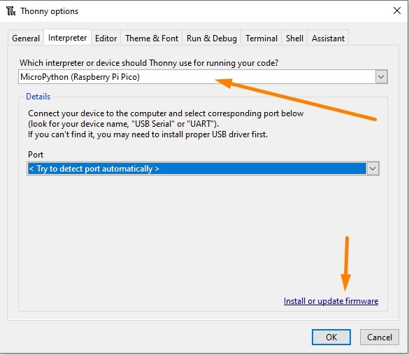
Go to Run > Select interpreter and choose MicroPython (Raspberry Pi Pico).
It's also a good idea to install or update firmware. This will update your Pico with the latest version of MicroPython, or install MicroPython if it wasn't already.
REPL interface (Shell)
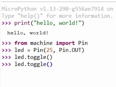
We can immediately start executing code in the REPL - Enter this code in the shell tab: print("Hello, World!")
The command will be sent to your Pico, which will execute the command and display back the message.
We can also take control of the on-board LED by executing the following code:
from machine import Pin
led = Pin(25, Pin.OUT)
led.toggle()
This code will toggle the LED. If you keep executing led.toggle() the LED will keep changing state.

Writing a Script
Create a new script with File > New and paste in the following code:
from machine import Pin
from time import sleep
led = Pin(25, Pin.OUT)
n = 0;
while True:
    led.toggle()
    print("13 x {} = {}".format(n, 13*n)) # print the thirteen-times table
    n = n + 1
    sleep(0.5)
Save the script - you will be prompted to save to your computer OR the pico. Select save to Pico and name the file main.py
Return to the REPL and press Ctrl+D (or use the Stop/Restart button) to restart your Pico. The LED should flash at a steady rate and the shell should begin printing multiples of thirteen.

Installing a Package
Packages are reusable pieces of code that another programmer has written for a common task, such as interfacing with a specific piece of hardware. Thonny has support for installing micropython packages from the Python Package Index - aka 'PyPI' directly onto the Raspberry Pi Pico.
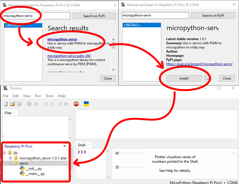
To install a package, ensure the Pico is plugged in and go to Tools > Manage Packages, which will show the Manage Packages dialog.
Enter the name of the package you would like to install into the search bar and click 'Search on PyPI'.
In the search results list, click the title of the package you would like to install. A title that's in bold simply indicates a direct search match on the text you entered in the search bar.
The Manage Packages dialog will show an overview of the package you have clicked. Click Install to install the package on your Pico.
You can confirm the package has been installed by checking the 'Raspberry Pi Pico' section of the File View in Thonny. The view should show a new folder named 'lib', and inside this folder will be one or more folders containing the metadata and source code of the library you just installed.
Conclusion
We've installed Thonny and uploaded scripts to our Raspberry Pi Pico - if you have any questions feel free to start the conversation below, or open a topic in our forums - we're full time makers and happy to help!
Good news! Thonny comes pre-installed with Raspberry Pi OS. However, to work with PiicoDev we need to enable I2C communications as follows:
- Power on your Raspberry Pi.
- Open the Preferences > Raspberry Pi Configuration, select the Interfaces tab
- Ensure I2C is Enabled
You only need to do this step for your first PiicoDev project - from here on you probably won't have to repeat this step when using PiicoDev hardware.

Let's get set up with scripting in Thonny for the Micro:bit. We'll install Thonny, configure for Micro:bit, and write our first script.
All you'll need to follow along is a Micro:bit v2 GO kit
Contents
- Install Thonny
- Set up Thonny
- REPL interface
- Writing a Script
- Useful Tips
- Uploading and Downloading Files
Install Thonny
Download Thonny here and run the installer.
Once the installer finishes, run Thonny.
Set up Thonny
Connect your Micro:bit V2 to your computer with the USB cable.

Open Thonny, and in the menu bar find Run > Select interpreter and choose MicroPython (BBC micro:bit)
It's also a good idea to install or update firmware. This will update your micro:bit with the latest version of MicroPython, or install MicroPython if it wasn't already.

Make sure the Files pane and Plotter are visible by selecting them in View > Files, and View > Plotter.
REPL interface (Shell)
Click the red STOP button to restart the MicroPython on your micro:bit if necessary. The Shell tab should display a block of text that indicates MicroPython is running:

We can immediately start executing code in the REPL - Enter this code in the shell tab: print("Hello, World!")
The command will be sent to your micro:bit, which will execute the command and display back the message - nice!
Next, we can also take control of the on-board speaker by executing the following code:
from microbit import *
import audio
audio.play(Sound.HAPPY)
This code will play a happy tone from the micro:bit's speaker! If you the LED. If you keep executing audio.play(Sound.HAPPY), the tone will repeat.

Writing a Script
The REPL is great for test-driving some new commands and performing short experiments - the real power is in scripting though.
Create a new script with File > New and paste in the following code:
from microbit import *
import audio

print("Hello!")

multiple = 1 # initialise the counter

while True:
    if button_a.was_pressed(): # get the next multiple of the thirteen
        result = multiple * 13 # Calculate the result
        print("13 times " + str(multiple) + " is " + str(result)) # print the multiplication
        multiple = multiple + 1 # increment the multiple

    if button_b.was_pressed(): # Say Hello
        display.show(Image.HAPPY)
        audio.play(Sound.HAPPY)
        display.clear()

    sleep(10) # a 10 millisecond delay
Save the script - you will be prompted to save to your computer OR the micro:bit. Select save to micro:bit and name the file main.py
Return to the REPL and press Ctrl+D to restart your micro:bit. If something went wrong, use the Stop/Restart button, then Ctrl+D.
Now, when we press the A button, the Shell will print the next multiple of 13, or if we press the B-button, our micro:bit gives us a smile and a hello sound.

Notice the plot is also showing some lines, and they're colour-coded to numbers in the print statement! In my case:
- The Blue line is the constant 13,
- The Orange Line is the multiple variable that increases slowly, and
- The Red line is the result variable, which increases really quickly.
Useful Tips
- You can stop a running script by selecting the Shell window and pressing Ctrl+C. This is useful if we want to make changes to the file(s) stored on the micro:bit.
- Reboot your micro:bit (or other MicroPython device) by selecting the Shell window and pressing Ctrl+D
- If something goes wrong, you can always click the red STOP button in the menu bar
Uploading and Downloading Files
We've been working with a file stored directly on the micro:bit - if you'd like to keep a copy on your computer, right-click the main.py file and select the 'download' option. Similarly, you can always upload code to your micro:bit by right-clicking files on your computer and selecting the upload button.

Conclusion
We've installed Thonny and uploaded our first script to our micro:bit. The script includes branches depending on which button is pressed and can generate audio tones and perform basic arithmetic. Now we can write scripts, move them between micro:bit and computer, or test code interactively using the REPL.
If you have any questions feel free to start the conversation below or open a topic in our forums - we're full-time makers and happy to help!
Let's get set up with scripting in Thonny for the Micro:bit. We'll install Thonny, configure for Micro:bit, and write our first script.
All you'll need to follow along is a Micro:bit v2 GO kit
Contents
- Install Thonny
- Set up Thonny
- REPL interface
- Writing a Script
- Useful Tips
- Uploading and Downloading Files
Install Thonny
Download Thonny here and run the installer.
Once the installer finishes, run Thonny.
Set up Thonny
Connect your Micro:bit V2 to your computer with the USB cable.
Open Thonny, and in the menu bar find Run > Select interpreter and choose MicroPython (BBC micro:bit)
It's also a good idea to install or update firmware. This will update your micro:bit with the latest version of MicroPython, or install MicroPython if it wasn't already.
Make sure the Files pane and Plotter are visible by selecting them in View > Files, and View > Plotter.
REPL interface (Shell)
Click the red STOP button to restart the MicroPython on your micro:bit if necessary. The Shell tab should display a block of text that indicates MicroPython is running:
We can immediately start executing code in the REPL - Enter this code in the shell tab: print("Hello, World!")
The command will be sent to your micro:bit, which will execute the command and display back the message - nice!
Next, we can also take control of the on-board speaker by executing the following code:
from microbit import *
import audio
audio.play(Sound.HAPPY)
This code will play a happy tone from the micro:bit's speaker! If you the LED. If you keep executing audio.play(Sound.HAPPY), the tone will repeat.
Writing a Script
The REPL is great for test-driving some new commands and performing short experiments - the real power is in scripting though.
Create a new script with File > New and paste in the following code:
from microbit import *
import audio

print("Hello!")

multiple = 1 # initialise the counter

while True:
    if button_a.was_pressed(): # get the next multiple of the thirteen
        result = multiple * 13 # Calculate the result
        print("13 times " + str(multiple) + " is " + str(result)) # print the multiplication
        multiple = multiple + 1 # increment the multiple

    if button_b.was_pressed(): # Say Hello
        display.show(Image.HAPPY)
        audio.play(Sound.HAPPY)
        display.clear()

    sleep(10) # a 10 millisecond delay
Save the script - you will be prompted to save to your computer OR the micro:bit. Select save to micro:bit and name the file main.py
Return to the REPL and press Ctrl+D to restart your micro:bit. If something went wrong, use the Stop/Restart button, then Ctrl+D.
Now, when we press the A button, the Shell will print the next multiple of 13, or if we press the B-button, our micro:bit gives us a smile and a hello sound.
Notice the plot is also showing some lines, and they're colour-coded to numbers in the print statement! In my case:
- The Blue line is the constant 13,
- The Orange Line is the multiple variable that increases slowly, and
- The Red line is the result variable, which increases really quickly.
Useful Tips
- You can stop a running script by selecting the Shell window and pressing Ctrl+C. This is useful if we want to make changes to the file(s) stored on the micro:bit.
- Reboot your micro:bit (or other MicroPython device) by selecting the Shell window and pressing Ctrl+D
- If something goes wrong, you can always click the red STOP button in the menu bar
Uploading and Downloading Files
We've been working with a file stored directly on the micro:bit - if you'd like to keep a copy on your computer, right-click the main.py file and select the 'download' option. Similarly, you can always upload code to your micro:bit by right-clicking files on your computer and selecting the upload button.
Conclusion
We've installed Thonny and uploaded our first script to our micro:bit. The script includes branches depending on which button is pressed and can generate audio tones and perform basic arithmetic. Now we can write scripts, move them between micro:bit and computer, or test code interactively using the REPL.
If you have any questions feel free to start the conversation below or open a topic in our forums - we're full-time makers and happy to help!
Download / Install PiicoDev Modules
To work with PiicoDev hardware, we need to download some drivers. The drivers provide all the functions to easily connect and communicate with PiicoDev hardware. Select your dev board from the options above.
We will need these files to work with the PiicoDev Servo Driver:
- Save the following files to your preferred coding directory - In this tutorial, we save to My Documents > PiicoDev.
- Download the PiicoDev Unified Library: PiicoDev_Unified.py (right-click, "save link as").
- Download the device module: PiicoDev_Servo.py (right-click, "save link as")
- Upload the files to your Pico. This process was covered in the Setup Thonny section.
The PiicoDev Unified Library is responsible for communicating with PiicoDev hardware, and the device module contains functions for driving specific PiicoDev devices.
We will now install/upgrade the PiicoDev python module for Thonny. This module contains all the drivers to work with all current PiicoDev hardware. Even if you have already installed the PiicoDev modules before, it's still worth upgrading to the latest version if one is available.
First, run Thonny by clicking the:
- Pi Start Menu
- Programming
- Thonny IDE

We need to set up a virtual environment to install the PiicoDev module into. This only needs to be done once as Thonny will remember an environment you have already made. If you are unsure if you have already set one up, you can always create a new one by following these steps.
To set up a virtual environment, click on run > configure interpreter, to open up the interpreter tab.

In this window, we can create a new virtual environment in the bottom right. A notification window will first pop up, just click OK.

In this window, we are going to create a new empty folder in our Home Directory which will be the location of our virtual environment. To do so follow these steps:
- Select the Home tab on the left-hand side of the window.
- Click the Create Folder button in the top right.
- Enter the name of the new folder. You can call it what you want, but we will call ours "myenv". Once you have written the name, click Create next to it.
- Click OK in the bottom left.

Thonny will then set up your virtual environment and when it has finished, it will return to the Interpreter tab. Click OK, and you will have successfully set up the environment.
Note: the Python Executable path now points to the environment we just created.
Remember, you only need to do this once as the next time you open Thonny it will use this environment.

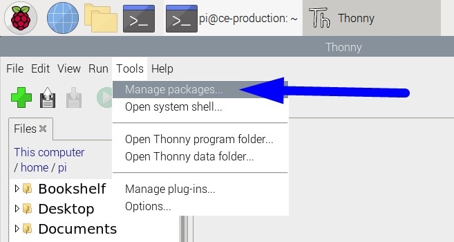
Next, open the package manager. From within Thonny click Tools > Manage Packages
Enter "piicodev" and click "Search on PyPI"

Finally, Install PiicoDev. If you already have PiicoDev installed, there may be an Upgrade button instead, to upgrade to a newer version.
With the PiicoDev module installed we are now ready to begin programming with PiicoDev hardware.

We will need these files to work with the PiicoDev Servo Driver:
- Save the following files to your preferred coding directory - In this tutorial, we save to My Documents > PiicoDev.
- Download the PiicoDev Unified Library: PiicoDev_Unified.py (right-click, "save link as").
- Download the device module: PiicoDev_Servo.py (right-click, "save link as")
- Upload the files to your micro:bit. This process was covered in the Setup Thonny section.
The PiicoDev Unified Library is responsible for communicating with PiicoDev hardware, and the device module contains functions for driving specific PiicoDev devices.
Example: Angular Servos
This example drives a servo to three angles (0°, 90°, 180°) sequentially, then smoothly sweeps the servo using a for loop.
The controller is first initialised with the PiicoDev_Servo_Driver() initialisation function, which returns a controller object.
Next, the servo is 'attached' to the controller with PiicoDev_Servo() which includes arguments for:
- controller - the controller object to attach a servo to
- channel - the channel number as indicated on the Servo Driver Module
- min_us (optional, default: 600) - the minimum expected pulse width in microseconds
- max_us (optional, default: 2400) - the maximum expected pulse width in microseconds
- degrees (optional, default 180) - the angular range of the servo in degrees. Generally 180°, though some servos may allow for more.
You can choose to omit values for min_us, max_us and degrees. If omitted, generally safe default values will be used.
With the controller initialised and the servo attached, driving the servo is as easy as setting the .angle attribute to some value 0->180.
# Drive an angular servo with generally safe-to-use default properties

from PiicoDev_Unified import sleep_ms
from PiicoDev_Servo import PiicoDev_Servo, PiicoDev_Servo_Driver

# Initialise the Servo Driver Module
controller = PiicoDev_Servo_Driver()

# Simple setup: Attach a servo to channel 1 of the controller with default properties
servo = PiicoDev_Servo(controller, 1)

# Customised setup - Attach a servo to channel 1 of the controller with the following properties:
#    - min_us: the minimum expected pulse length (microsecconds)
#    - max_us: the maximum expected pulse length (microsecconds)
#    - degrees: the angular range of the servo in degrees
# Uncomment the line below to use customised properties
# servo = PiicoDev_Servo(controller, 1, min_us=600, max_us=2400, degrees=180)

# Step the servo
servo.angle = 0
sleep_ms(1000)
servo.angle = 90
sleep_ms(1000)
servo.angle = 180
sleep_ms(1000)
servo.angle = 0
sleep_ms(2000)

# Sweep the servo slowly 0->180°
for x in range(0,180,5):
    servo.angle = x
    sleep_ms(40)
Example: Continuous Rotation Servos
Continuous rotation servos are set up in a similar fashion to the previous example - we can simply ignore the degrees attribute.
To drive a continuous rotation servo, we use the .speed attribute which accepts values between -1.0 (full-speed reverse) and 1.0 (full-speed forward). A value of 0.0 is stop.
# Drive a Continuous Rotation (a.k.a. 360 degree) servo.

from PiicoDev_Unified import sleep_ms
from PiicoDev_Servo import PiicoDev_Servo, PiicoDev_Servo_Driver

controller = PiicoDev_Servo_Driver()

continuous_servo = PiicoDev_Servo(controller, 1, midpoint_us=1500, range_us=1800) # Connect a 360° servo to channel 2


continuous_servo.speed = 1    # fast
sleep_ms(1000)
continuous_servo.speed = 0.2  # slow
sleep_ms(1000)

continuous_servo.speed = -0.2 # slow reverse
sleep_ms(1000)
continuous_servo.speed = -1   # fast reverse
sleep_ms(1000)

continuous_servo.speed = 0    # stop
Technical Aside: Tuning the Zero-Point
You may notice your servo does not completely stop when .speed=0 - this is normal for continuous rotation servos as they don't have a feedback loop like a positional servo. There are two paths forward here:
Some servos have a tuning potentiometer, adjust this with a screwdriver until the servo stops rotating.
For servos without a tuning pot, you can use some additional arguments: midpoint_us and range_us. These do the same job as min_us and max_us which is to set the pulse range of the servo, it's just a little simpler for tuning continuous servos to think in terms of midpoint.
- midpoint_us will set the midpoint pulse in milliseconds. Try a starting value of 1500 and make adjustments until the servo is stopped when .speed=0
- range_us sets the range of pulse widths to send. It's the same as => max_us - min_us = range_us
Note: Both midpoint and range must be set during initialisation. It is not enough to specify just one.
For example, perhaps a servo does not have a tuning pot and I've found empirically that the midpoint is actually 1520us. The initialisation for this servo could look something like this:
continuous_servo = PiicoDev_Servo(controller, 2, midpoint_us=1520, range_us=1800)
Example: Connecting Multiple Servo Drivers Together
It's possible to connect up to four PiicoDev Servo Driver Modules together on the same PiicoDev bus to drive a total of 16 servos. For this to work we need to satisfy some conditions:
- Each Servo Driver has a unique Address Switch (ASW) setting
- Each Servo Driver is initialised (in code) with its corresponding ASW setting
- Each Servo Driver has an adequate power supply
Address Switch ASW
This is the easy part - use a fine pen or similar to set the 2-position switch to a unique combination. Since there are two switch positions, there are four unique switch combinations.

Initialisation Code
We need to provide the ASW configuration when we initialise the Servo Driver. This is an additional argument asw=[#,#] where we encode the switch positions. For example, to initialise a Servo Driver with the following switch positions ASW:1 = ON, ASW:2 = OFF, we would use:
controller_B = PiicoDev_Servo_Driver( asw=[1,0] )
Power Supply
Each Servo Driver needs adequate power to drive its connected servos. The amount of power depends on the number of servos that will be running at the same time, their size, and how much torque they're expected to produce. A rule of thumb is that each small servo needs about 0.8A when moving, and larger servos need as much as 2.5A to move. Depending on your project, you may only need a single servo active at any one time, or all four channels firing at the same time - and this will drastically change how you power each servo module. For projects with multiple Servo Drivers but no simultaneous servo activity, you may daisy-chain power between Servo Modules using a USB-C cable. For high-power projects, it might be more appropriate to power each Servo Driver individually.
We found that even though this example is driving eight servos, the hardware only draws about 1.1A, since the servos are not delivering high torque and are turning very slowly.
Controlling Eight Servos across Two Servo Drivers
The demonstration shown towards the end of the tutorial video shows off a nice wavy demonstration using eight servos connected to two servo drivers. The complete code is listed below for reference. Of course, this example can be picked apart and repurposed as you see fit.
# Drive eight angular servos with generally safe-to-use default properties
# This requires two PiicoDev Servo Drivers
# Set all the ASW switches OFF on the first Driver (controller_A)
# Set ASW:1 ON, ASW:2 OFF for on the second Driver (controller_B)
from math import sin
from PiicoDev_Unified import sleep_ms
from PiicoDev_Servo import PiicoDev_Servo, PiicoDev_Servo_Driver

# Initialise the Servo Driver Module
controller = PiicoDev_Servo_Driver()

# Initialise the Servo Driver Module
controller_A = PiicoDev_Servo_Driver(asw=[0,0])
controller_B = PiicoDev_Servo_Driver(asw=[1,0])

# Setup four servos, each on a different channel of controller_A
servo1 = PiicoDev_Servo(controller_A, 1)
servo2 = PiicoDev_Servo(controller_A, 2)
servo3 = PiicoDev_Servo(controller_A, 3)
servo4 = PiicoDev_Servo(controller_A, 4)

# Setup four more servos, each on a different channel of controller_B
servo5 = PiicoDev_Servo(controller_B, 1)
servo6 = PiicoDev_Servo(controller_B, 2)
servo7 = PiicoDev_Servo(controller_B, 3)
servo8 = PiicoDev_Servo(controller_B, 4)

# Create a list we can loop through
servos = [servo1, servo2, servo3, servo4, servo5, servo6, servo7, servo8]

theta=0      # the control variable that drives all the servos
offset = 0.5 # difference between each servo

while True:
    for i in range(len(servos)):
        x = 90 + 90*sin(theta - (i+1)*0.25) # Compute a unique angle for each servo
        servos[i].angle = x

    theta += 0.1 # incrementing theta will move the servos a small amount on the next loop
    sleep_ms(20)
Conclusion
Motion makes a project pretty exciting, and the PiicoDev Servo Driver can bring a lot of motion. We've seen how to control angular and continuous-rotation servos, how to drive multiple servos, and how to daisy chain multiple drivers together. From here it's up to you! Perhaps you're interested in making a wheeled robot with continuous servos... Perhaps you want to add a grabby claw to your robot using angular servos! Whatever you make, show it off in the comments below!
Happy Making!

