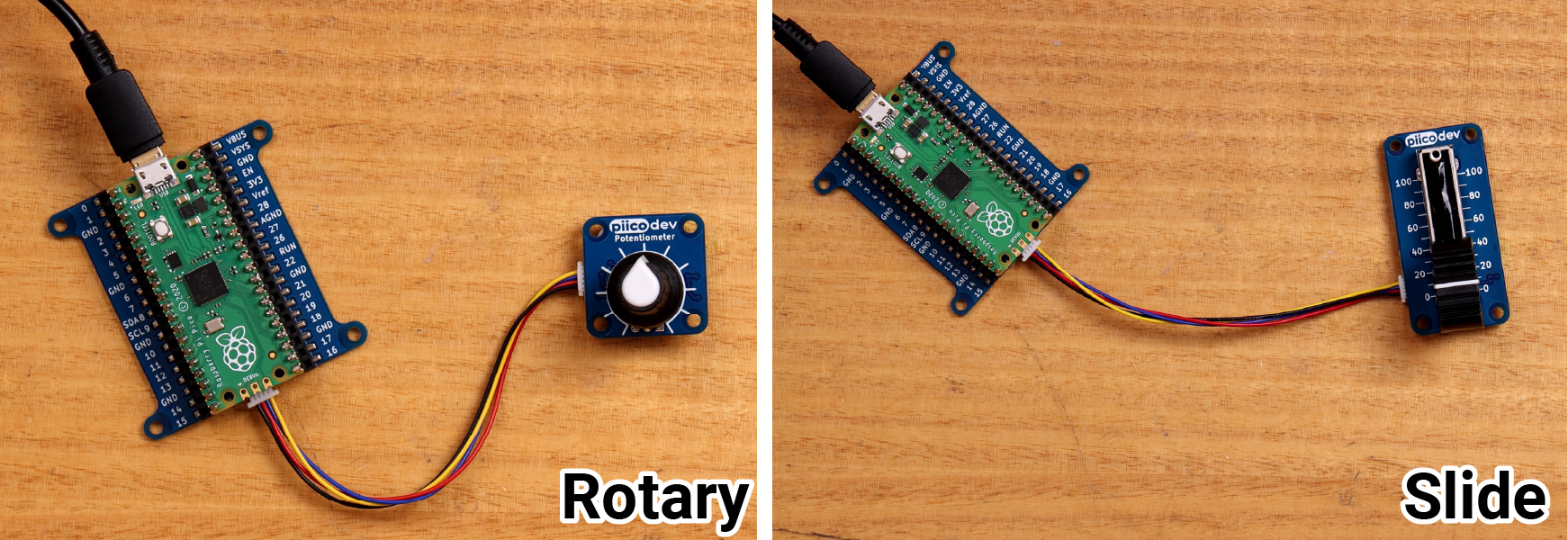
This guide will help you get started with a PiicoDev® Potentiometer - an intuitive input device that allows you to easily interact with your project. PiicoDev Potentiometers are available in two flavours: Rotary and Slider. We'll walk through some examples to read from the potentiometer and look at some extra features like changing the output scale.
Potentiometers or "pots" are a ubiquitous user interface - you'll see them on audio amplifiers, mixing desks, lab gear and power supplies, and plenty of other equipment where an analogue control is required.
To get started - select your dev. board below.
Hardware and Connections
To follow along you'll need:
- A Raspberry Pi Pico (with Soldered Headers) or Pico W (with Soldered Headers)
- A PiicoDev Potentiometer or PiicoDev Slide Potentiometer
- A PiicoDev Expansion Board for Raspberry Pi Pico
- A PiicoDev Cable
- (Optional) A PiicoDev Platform will keep everything mounted securely.
Plug your Pico into the expansion board. Make sure it is plugged in the correct orientation - Pin 0 on the expansion board should be to the left of the Pico's USB connector.
Connect your Pot to the expansion board with a PiicoDev Cable.
To follow along you'll need:
- A Raspberry Pi single board computer (Pictured: Raspberry Pi 4 Model B)
- A PiicoDev Potentiometer or PiicoDev Slide Potentiometer
- A PiicoDev Adapter for Raspberry Pi
- A PiicoDev Cable (100mm or longer is best for Raspberry Pi)
- (Optional) A PiicoDev Platform will keep everything mounted securely.
Mount the Adapter onto your Pi's GPIO. Make sure it is plugged in the correct orientation - An arrow on the Adapter will point to the Pi's Ethernet connector (on a Pi 3 the Ethernet connector and USB ports are swapped.)
Connect your Pot to the Adapter with a PiicoDev Cable.

To follow along you'll need:
- A micro:bit v2
- A PiicoDev Potentiometer or PiicoDev Slide Potentiometer
- A PiicoDev Adapter for micro:bit
- A PiicoDev Cable
- (Optional) A PiicoDev Platform will keep everything mounted securely.
Plug your micro:bit into the Adapter, making sure the buttons on the micro:bit are facing up.
Connect your Pot to the Adapter with a PiicoDev Cable.

Setup Thonny
Select your dev board from the tabs above to get ready for programming with Thonny for the first time.
If you have already programmed with PiicoDev modules before, there's probably no need to follow these steps again.
Let's get set up with scripting in Thonny for the Raspberry Pi Pico.
We'll install Thonny, configure for Pico and write our first script. To follow along you'll need:
Install Thonny
If you're working on a Raspberry Pi 4, you're in luck - Thonny comes pre-installed. For those on another operating system, download Thonny here and run the installer.
Once the installer finishes, run Thonny.
Set up Thonny
Hold the BOOTSEL button on your Pico, and connect your Pico to your computer via USB.
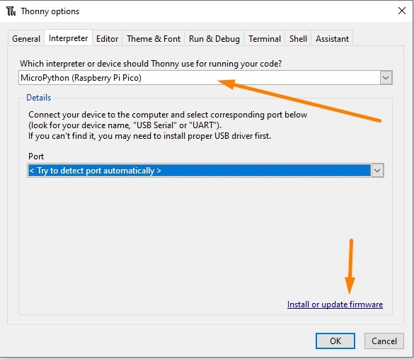
Go to Run > Select interpreter and choose MicroPython (Raspberry Pi Pico).
It's also a good idea to install or update firmware. This will update your Pico with the latest version of MicroPython, or install MicroPython if it wasn't already.
REPL interface (Shell)
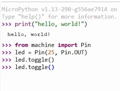
We can immediately start executing code in the REPL - Enter this code in the shell tab: print("Hello, World!")
The command will be sent to your Pico, which will execute the command and display back the message.
We can also take control of the on-board LED by executing the following code:
from machine import Pin
led = Pin(25, Pin.OUT)
led.toggle()
This code will toggle the LED. If you keep executing led.toggle() the LED will keep changing state.

Writing a Script
Create a new script with File > New and paste in the following code:
from machine import Pin
from time import sleep
led = Pin(25, Pin.OUT)
n = 0;
while True:
    led.toggle()
    print("13 x {} = {}".format(n, 13*n)) # print the thirteen-times table
    n = n + 1
    sleep(0.5)
Save the script - you will be prompted to save to your computer OR the pico. Select save to Pico and name the file main.py
Return to the REPL and press Ctrl+D (or use the Stop/Restart button) to restart your Pico. The LED should flash at a steady rate and the shell should begin printing multiples of thirteen.

Installing a Package
Packages are reusable pieces of code that another programmer has written for a common task, such as interfacing with a specific piece of hardware. Thonny has support for installing micropython packages from the Python Package Index - aka 'PyPI' directly onto the Raspberry Pi Pico.
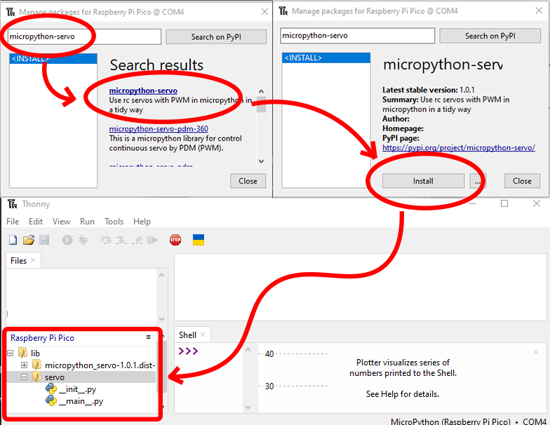
To install a package, ensure the Pico is plugged in and go to Tools > Manage Packages, which will show the Manage Packages dialog.
Enter the name of the package you would like to install into the search bar and click 'Search on PyPI'.
In the search results list, click the title of the package you would like to install. A title that's in bold simply indicates a direct search match on the text you entered in the search bar.
The Manage Packages dialog will show an overview of the package you have clicked. Click Install to install the package on your Pico.
You can confirm the package has been installed by checking the 'Raspberry Pi Pico' section of the File View in Thonny. The view should show a new folder named 'lib', and inside this folder will be one or more folders containing the metadata and source code of the library you just installed.
Conclusion
We've installed Thonny and uploaded scripts to our Raspberry Pi Pico - if you have any questions feel free to start the conversation below, or open a topic in our forums - we're full time makers and happy to help!
Good news! Thonny comes pre-installed with Raspberry Pi OS. However, to work with PiicoDev we need to enable I2C communications as follows:
- Power on your Raspberry Pi.
- Open the Preferences > Raspberry Pi Configuration, select the Interfaces tab
- Ensure I2C is Enabled
You only need to do this step for your first PiicoDev project - from here on you probably won't have to repeat this step when using PiicoDev hardware.

Let's get set up with scripting in Thonny for the Micro:bit. We'll install Thonny, configure for Micro:bit, and write our first script.
All you'll need to follow along is a Micro:bit v2 GO kit
Contents
- Install Thonny
- Set up Thonny
- REPL interface
- Writing a Script
- Useful Tips
- Uploading and Downloading Files
Install Thonny
Download Thonny here and run the installer.
Once the installer finishes, run Thonny.
Set up Thonny
Connect your Micro:bit V2 to your computer with the USB cable.

Open Thonny, and in the menu bar find Run > Select interpreter and choose MicroPython (BBC micro:bit)
It's also a good idea to install or update firmware. This will update your micro:bit with the latest version of MicroPython, or install MicroPython if it wasn't already.

Make sure the Files pane and Plotter are visible by selecting them in View > Files, and View > Plotter.
REPL interface (Shell)
Click the red STOP button to restart the MicroPython on your micro:bit if necessary. The Shell tab should display a block of text that indicates MicroPython is running:

We can immediately start executing code in the REPL - Enter this code in the shell tab: print("Hello, World!")
The command will be sent to your micro:bit, which will execute the command and display back the message - nice!
Next, we can also take control of the on-board speaker by executing the following code:
from microbit import *
import audio
audio.play(Sound.HAPPY)
This code will play a happy tone from the micro:bit's speaker! If you the LED. If you keep executing audio.play(Sound.HAPPY), the tone will repeat.

Writing a Script
The REPL is great for test-driving some new commands and performing short experiments - the real power is in scripting though.
Create a new script with File > New and paste in the following code:
from microbit import *
import audio

print("Hello!")

multiple = 1 # initialise the counter

while True:
    if button_a.was_pressed(): # get the next multiple of the thirteen
        result = multiple * 13 # Calculate the result
        print("13 times " + str(multiple) + " is " + str(result)) # print the multiplication
        multiple = multiple + 1 # increment the multiple

    if button_b.was_pressed(): # Say Hello
        display.show(Image.HAPPY)
        audio.play(Sound.HAPPY)
        display.clear()

    sleep(10) # a 10 millisecond delay
Save the script - you will be prompted to save to your computer OR the micro:bit. Select save to micro:bit and name the file main.py
Return to the REPL and press Ctrl+D to restart your micro:bit. If something went wrong, use the Stop/Restart button, then Ctrl+D.
Now, when we press the A button, the Shell will print the next multiple of 13, or if we press the B-button, our micro:bit gives us a smile and a hello sound.

Notice the plot is also showing some lines, and they're colour-coded to numbers in the print statement! In my case:
- The Blue line is the constant 13,
- The Orange Line is the multiple variable that increases slowly, and
- The Red line is the result variable, which increases really quickly.
Useful Tips
- You can stop a running script by selecting the Shell window and pressing Ctrl+C. This is useful if we want to make changes to the file(s) stored on the micro:bit.
- Reboot your micro:bit (or other MicroPython device) by selecting the Shell window and pressing Ctrl+D
- If something goes wrong, you can always click the red STOP button in the menu bar
Uploading and Downloading Files
We've been working with a file stored directly on the micro:bit - if you'd like to keep a copy on your computer, right-click the main.py file and select the 'download' option. Similarly, you can always upload code to your micro:bit by right-clicking files on your computer and selecting the upload button.

Conclusion
We've installed Thonny and uploaded our first script to our micro:bit. The script includes branches depending on which button is pressed and can generate audio tones and perform basic arithmetic. Now we can write scripts, move them between micro:bit and computer, or test code interactively using the REPL.
If you have any questions feel free to start the conversation below or open a topic in our forums - we're full-time makers and happy to help!
Let's get set up with scripting in Thonny for the Micro:bit. We'll install Thonny, configure for Micro:bit, and write our first script.
All you'll need to follow along is a Micro:bit v2 GO kit
Contents
- Install Thonny
- Set up Thonny
- REPL interface
- Writing a Script
- Useful Tips
- Uploading and Downloading Files
Install Thonny
Download Thonny here and run the installer.
Once the installer finishes, run Thonny.
Set up Thonny
Connect your Micro:bit V2 to your computer with the USB cable.
Open Thonny, and in the menu bar find Run > Select interpreter and choose MicroPython (BBC micro:bit)
It's also a good idea to install or update firmware. This will update your micro:bit with the latest version of MicroPython, or install MicroPython if it wasn't already.
Make sure the Files pane and Plotter are visible by selecting them in View > Files, and View > Plotter.
REPL interface (Shell)
Click the red STOP button to restart the MicroPython on your micro:bit if necessary. The Shell tab should display a block of text that indicates MicroPython is running:
We can immediately start executing code in the REPL - Enter this code in the shell tab: print("Hello, World!")
The command will be sent to your micro:bit, which will execute the command and display back the message - nice!
Next, we can also take control of the on-board speaker by executing the following code:
from microbit import *
import audio
audio.play(Sound.HAPPY)
This code will play a happy tone from the micro:bit's speaker! If you the LED. If you keep executing audio.play(Sound.HAPPY), the tone will repeat.
Writing a Script
The REPL is great for test-driving some new commands and performing short experiments - the real power is in scripting though.
Create a new script with File > New and paste in the following code:
from microbit import *
import audio

print("Hello!")

multiple = 1 # initialise the counter

while True:
    if button_a.was_pressed(): # get the next multiple of the thirteen
        result = multiple * 13 # Calculate the result
        print("13 times " + str(multiple) + " is " + str(result)) # print the multiplication
        multiple = multiple + 1 # increment the multiple

    if button_b.was_pressed(): # Say Hello
        display.show(Image.HAPPY)
        audio.play(Sound.HAPPY)
        display.clear()

    sleep(10) # a 10 millisecond delay
Save the script - you will be prompted to save to your computer OR the micro:bit. Select save to micro:bit and name the file main.py
Return to the REPL and press Ctrl+D to restart your micro:bit. If something went wrong, use the Stop/Restart button, then Ctrl+D.
Now, when we press the A button, the Shell will print the next multiple of 13, or if we press the B-button, our micro:bit gives us a smile and a hello sound.
Notice the plot is also showing some lines, and they're colour-coded to numbers in the print statement! In my case:
- The Blue line is the constant 13,
- The Orange Line is the multiple variable that increases slowly, and
- The Red line is the result variable, which increases really quickly.
Useful Tips
- You can stop a running script by selecting the Shell window and pressing Ctrl+C. This is useful if we want to make changes to the file(s) stored on the micro:bit.
- Reboot your micro:bit (or other MicroPython device) by selecting the Shell window and pressing Ctrl+D
- If something goes wrong, you can always click the red STOP button in the menu bar
Uploading and Downloading Files
We've been working with a file stored directly on the micro:bit - if you'd like to keep a copy on your computer, right-click the main.py file and select the 'download' option. Similarly, you can always upload code to your micro:bit by right-clicking files on your computer and selecting the upload button.
Conclusion
We've installed Thonny and uploaded our first script to our micro:bit. The script includes branches depending on which button is pressed and can generate audio tones and perform basic arithmetic. Now we can write scripts, move them between micro:bit and computer, or test code interactively using the REPL.
If you have any questions feel free to start the conversation below or open a topic in our forums - we're full-time makers and happy to help!
Download / Install PiicoDev Modules
To work with PiicoDev hardware, we need to download some drivers. The drivers provide all the functions to easily connect and communicate with PiicoDev hardware. Select your dev board from the options above.
We will need these files to easily drive the PiicoDev Potentiometer:
- Save the following files to your preferred coding directory - In this tutorial, we save to My Documents > PiicoDev.
- Download the PiicoDev Unified Library: PiicoDev_Unified.py (right-click, "save link as").
- Download the device module: PiicoDev_Potentiometer.py (right-click, "save link as")
- Upload the files to your Pico. This process was covered in the Setup Thonny section.
The PiicoDev Unified Library is responsible for communicating with PiicoDev hardware, and the device module contains functions for driving specific PiicoDev devices.
We will now install/upgrade the PiicoDev python module for Thonny. This module contains all the drivers to work with all current PiicoDev hardware. Even if you have already installed the PiicoDev modules before, it's still worth upgrading to the latest version if one is available.
First, run Thonny by clicking the:
- Pi Start Menu
- Programming
- Thonny IDE

We need to set up a virtual environment to install the PiicoDev module into. This only needs to be done once as Thonny will remember an environment you have already made. If you are unsure if you have already set one up, you can always create a new one by following these steps.
To set up a virtual environment, click on run > configure interpreter, to open up the interpreter tab.

In this window, we can create a new virtual environment in the bottom right. A notification window will first pop up, just click OK.

In this window, we are going to create a new empty folder in our Home Directory which will be the location of our virtual environment. To do so follow these steps:
- Select the Home tab on the left-hand side of the window.
- Click the Create Folder button in the top right.
- Enter the name of the new folder. You can call it what you want, but we will call ours "myenv". Once you have written the name, click Create next to it.
- Click OK in the bottom left.

Thonny will then set up your virtual environment and when it has finished, it will return to the Interpreter tab. Click OK, and you will have successfully set up the environment.
Note: the Python Executable path now points to the environment we just created.
Remember, you only need to do this once as the next time you open Thonny it will use this environment.

Next, open the package manager. From within Thonny click Tools > Manage Packages
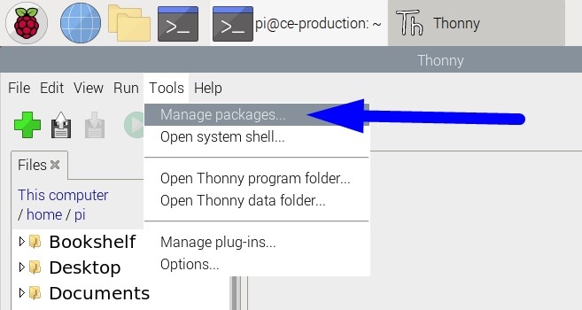
Enter "piicodev" and click "Search on PyPI"

Finally, Install PiicoDev. If you already have PiicoDev installed, there may be an Upgrade button instead, to upgrade to a newer version.
With the PiicoDev module installed we are now ready to begin programming with PiicoDev hardware.

We will need these files to easily drive the PiicoDev Potentiometer:
- Save the following files to your preferred coding directory - In this tutorial, we save to My Documents > PiicoDev.
- Download the PiicoDev Unified Library: PiicoDev_Unified.py (right-click, "save link as").
- Download the device module: PiicoDev_Potentiometer.py (right-click, "save link as")
- Upload the files to your micro:bit. This process was covered in the Setup Thonny section.
The PiicoDev Unified Library is responsible for communicating with PiicoDev hardware, and the device module contains functions for driving specific PiicoDev devices.
Reading Values & Changing the Scale
We're ready to begin reading from our PiicoDev Potentiometer! The following example prints the value of the pot to the shell.
# Read the PiicoDev Potentiometer value
from PiicoDev_Potentiometer import PiicoDev_Potentiometer
from PiicoDev_Unified import sleep_ms

pot = PiicoDev_Potentiometer() # Initialise the potentiometer
pot.maximum = 100 # set the range of output values
pot.minimum = 0   # if minimum or maximum are ommitted, they will default to 0 and 100 respectively

while True:
    print(pot.value) # read the pot and print the result
    sleep_ms(100)
By default, the PiicoDev Potentiometer outputs a value between 0.0 (at the minimum of the scale) and 100.0 at the maximum of the scale. These limits are easy to change by setting the .minimum and .maximum properties. You can put whatever values you want in these! The nomenclature minimum and maximum refer to the pot's end-of-travel, so you can invert the direction by setting .minimum=100 and .maximum=0. You can even use negative numbers if you wish! Try configuring the potentiometer to output values between -1 and 1.
Code Remix
We'll use a pot to control the brightness of the Pico's on-board LED. This example shows how easy it is to control real, physical hardware with a Pot. By rescaling the pot using minimum and maximum, we don't have to do any extra processing to turn the Pot's value into an appropriate PWM value (for duty_u16()).
According to the MicroPython Documentation, a values between 0-65535 correspond to 0-100% duty cycle. We found that a value of 65535 produces flickering, so we chose 65534.
# Remix: Control the brightness of the Pico's LED with a PiicoDev Potentiometer
from PiicoDev_Potentiometer import PiicoDev_Potentiometer
from PiicoDev_Unified import sleep_ms
from machine import Pin, PWM

led = PWM(Pin(25)) # Initialise the pin connected to the onboard LED as a PWM channel

pot = PiicoDev_Potentiometer(minimum=0, maximum=65534) # Scale the pot to the duty cycle range for a Raspberry Pi Pico

while True:
    duty = round(pot.value)
    led.duty_u16( duty )
    sleep_ms(20)
We'll now use the PiicoDev Potentiometer to control some hardware. The Raspberry Pi doesn't have any onboard hardware that we can control for this example, but we do have control of the power LED on the PiicoDev Potentiometer. The LED will always turn on at power-up, but we can control it afterwards with code. In this example, we'll use the pot to control how fast the LED flashes. To do this, we'll rescale the pot to create a delay between 300 and 100 milliseconds
# Use the potentiometer as a control input - change the flash speed of the on-board LED
from PiicoDev_Potentiometer import PiicoDev_Potentiometer
from PiicoDev_Unified import sleep_ms

# Initialise the module - here the range corresponds to millisecond delays
pot = PiicoDev_Potentiometer(minimum=500, maximum=50)

while True:
    delay_ms = int(pot.value)    # sample the pot, we know the value is already useful as milliseconds
    pot.led = not pot.led        # toggle the LED

    hz = round(1000/delay_ms/2, 1) # convert delay [ms] to frequency [Hz]
    print('Flash rate ' + str(hz) + ' Hz')

    sleep_ms(delay_ms)           # wait for the delay time
The micro:bit features an onboard buzzer - let's rescale the PiicoDev Potentiometer to work like a tone knob, changing the frequency of a tone. To do this, we'll need to import music, and call the music.pitch() method to generate a tone. The argument we provide music.pitch() will be a frequency. We can rescale the pot to give an audible range of frequencies. Thanks to a quirk of how the pitch() function works, no tone is created if we pass it a negative frequency. We can take advantage of this by scaling our Pot from -1 to 440 Hz. This means that when the pot is at the minimum end of the scale (-1) the buzzer will turn off.
# Use a PiicoDev Potentiometer to control the tone of a micro:bit's buzzer
from PiicoDev_Potentiometer import PiicoDev_Potentiometer
from PiicoDev_Unified import sleep_ms
import music

pot = PiicoDev_Potentiometer() # Initialise the potentiometer as a frequency-control
pot.maximum = 440 # Hz
pot.minimum = -1 # micro:bit will constantly "tick" if using 0Hz, so we'll use -1 for 'no sound'

while True:
    frequency = int(pot.value) # pitch() accepts whole-numbers only!
    music.pitch(frequency)
    print(frequency, 'Hz') # read the pot and print the result
    sleep_ms(100)
Multiple Potentiometers
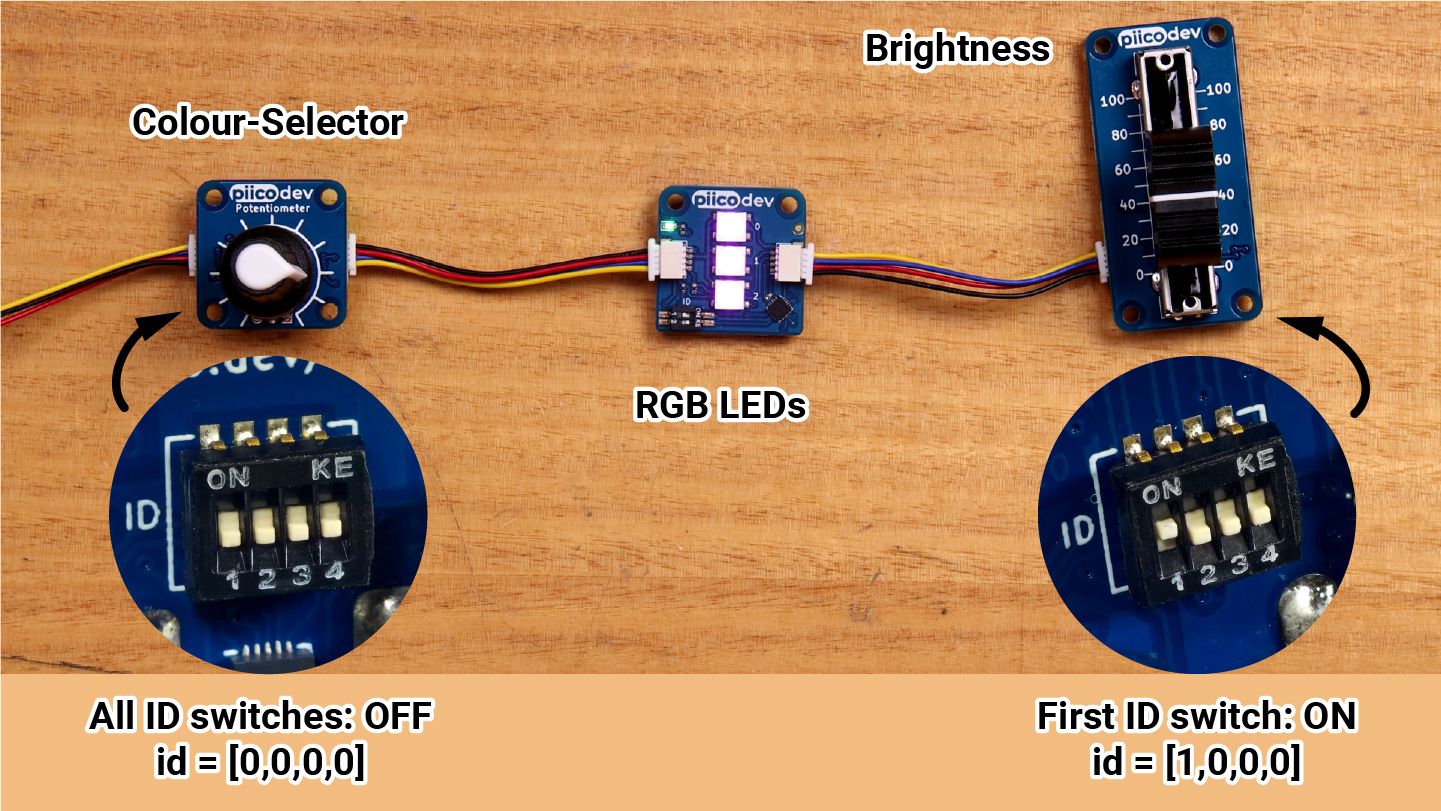
It is possible to connect to more than one PiicoDev Potentiometer at the same time. The following example uses two PiicoDev Potentiometers and a PiicoDev RGB LED module to create a lighting controller. One Pot controls Colour (hue) and the other controls Brightness. We will set up the colour-controlling pot to have all its ID switches OFF. The Brightness-controlling pot will have its ID #1 switch set to ON. Referring to the example code, we can see each Pot is initialised with an id argument which encodes the positions of the ID switches (1=ON, 0=OFF).
# Lighting controller example
# One Pot controls the Hue (0 -> 1), one pot controls Brightness (0 -> 255)

from PiicoDev_Potentiometer import PiicoDev_Potentiometer
from PiicoDev_RGB import PiicoDev_RGB, wheel
from PiicoDev_Unified import sleep_ms

colour = PiicoDev_Potentiometer(minimum=0, maximum=1,   id=[0,0,0,0])
brightness = PiicoDev_Potentiometer(minimum=0, maximum=255 ,id=[1,0,0,0])
leds = PiicoDev_RGB(id=[0,1,0,0]) # all devices with 'id' switches require a unique 'id' switch setting - even if they're a different type of module.

while True:
    # Sample the pots for colour and brightness
    c = colour.value
    b = int(brightness.value)

    print(c*255, b) # print a line for each pot (scale up the colour)

    # Set the LED colour and brightness
    leds.fill( wheel(c) )
    leds.setBrightness(b)

    sleep_ms(50)
Conclusion & Resources
We can now user PiicoDev Potentiometers as intuitive control inputs for our projects. Re-scaling the pot (changing its maximum and minimum) is convenient since we don't need to write additional code to modify the Pot's output value. Connecting multiple Pots is as simple as assigning them unique IDs. We've seen how all these features come together to create a simple lighting controller project, where a different pot controls properties of a multicoloured light.
If you're looking for some inspiration, check out the PiicoDev Sketcher Project - use two Pots and a Display to build a creative sketching toy!
For additional resources on how to use the PiicoDev Potentiometer API, read the Documentation.

