Print-in-Place mechanism is one of the special things about additive manufacturing that all other manufacturing methods just cannot replicate. They use various hinges, linkages and joints to create moving parts that are printed as a single task. No assembly required. Then if you get really good at it you can even 3D print models that unfold to be much larger than the size of your build plate. Print-in-Place is truly the holy grail of additive manufacturing. It requires the pinnacle of design and a high understanding of both material properties and how they act when you print them. Also, knowledge of how slicers interpret and create recipes from a CAD design is crucially needed. So with that in mind, let us crack on in!
I have been printing several print-in-place components from CPE + White, Nylon and PLA on an Ultimaker 3/Ultimaker S5. I have been printing commonly seen print-in-place designs found online on any good STL database. The game-plan is to demonstrate that differences in Cura settings are needed between materials to get Print-in-Place mechanisms to work. I have dialled in the Ultimaker 3 for these materials but when it comes to making Print-in-Place designs work correctly the most crucial setting to get right is Horizontal Expansion. You can have a great looking 3D print but if the movement is locked up and not work, no bueno.
So this guide will give the tools to print great Print-in-Place models consistently by utilising slicing software.
- Horizontal Expansion Explained
- My Trick to get Horizontal Expansion Consistently Correct
- Other Settings Worth Nailing
Printing in this manner brings up a whole bunch of factors to pay attention to so it is important very important that the models you are creating from your 3D printer are top-notch. Check out the guide Improving 3D Printed Models to learn excellent ways to do just that. Cura is the slicing software focused on in this guide however any slicer worth its salt will have the option to adjust Horizontal Expansion. In Prusa Slicer, this setting is called XY Size Compensation. If this is your first time encountering Ultimaker Cura check out the Overview Guide for Makers.
As always if you've got any questions, queries or things you'd like to see added please let us know your thoughts!
Horizontal Expansion Explained
Horizontal expansion is the amount of offset applied to all polygons in each layer. Positive values will compensate for too large holes and negative values can compensate for too small holes. So, this setting will alter the dimension in the XY planes in millimetre increments. Now, this is worth remembering, if you are creating models to a certain specification this setting will alter the CAD model away from the original size.
What does this mean in practice? Allow me to demonstrate, below you can see three variations of the same model sliced in Ultimaker Cura with different horizontal expansion values. From left to right each model has a horizontal expansion setting of; -1.6mm, -0.2mm and 0.8mm. This comparison clearly shows what massive changes in this setting can do to a CAD model.
This setting is also a fantastic tool to compensate for the deviation of your particular 3D printer. Print out a couple of 10mm holes, see what they come out as and adjust accordingly for future prints where dimensional accuracy is essential. Make sure you re-do this process for different materials as the thermal expansion co-efficient and dimensional stability after phase transitions are unique for each material.
My Trick to get Horizontal Expansion Consistently Correct
It is all about using your eyes and getting it right one time with the particular material of a particular design. Unfortunately, Cura does not have a measure feature inside it (Criminal if you ask me). Now before going to deep, if you don't trust your eyes there are extensions you can add to Cura which you can use which give a semblance of a measuring tape. Another option is creating a square box using the shortcut E and then clicking on the model you can create a cube (used normally for support blocking) which will have the dimension of 10mm by 10mm by 10 mm. You can then scale this cube to the size you want to measure and overlay it over the CAD model and get a very good idea from it. This is also a good method for measuring hole diameters. See below for an example of this, knowing that the one exposed side of the support blocker is 10mm long you can get a good understanding of the diameter of the hinge.
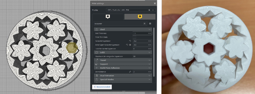
The method I use with the best success is comparing a very successful sliced print-in-place to the new print-in-place I want to print. Then I adjust the horizontal expansion of the new model to have very similar gaps to that very successful print-in-place print. Below is an image of a very successful print I had using CPE + on an Ultimaker 3. To get to this stage it did require some trial and error. Most files you find online are created with PLA in mind so the initial stage of getting new material to work with a 3D printer will require this trial and error. Holy grail and all that. See below for the sliced file and the final piece that I use to compare for all CPE + Print-In-Place Models.
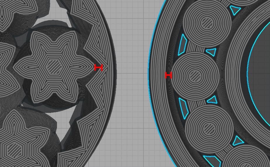
Below is me comparing this current set-up to a new model that I would like to 3D print. As you can see the walls between parts are much closer than the grail model. This means it would likely fuse together and not work when pulled from the build platform.
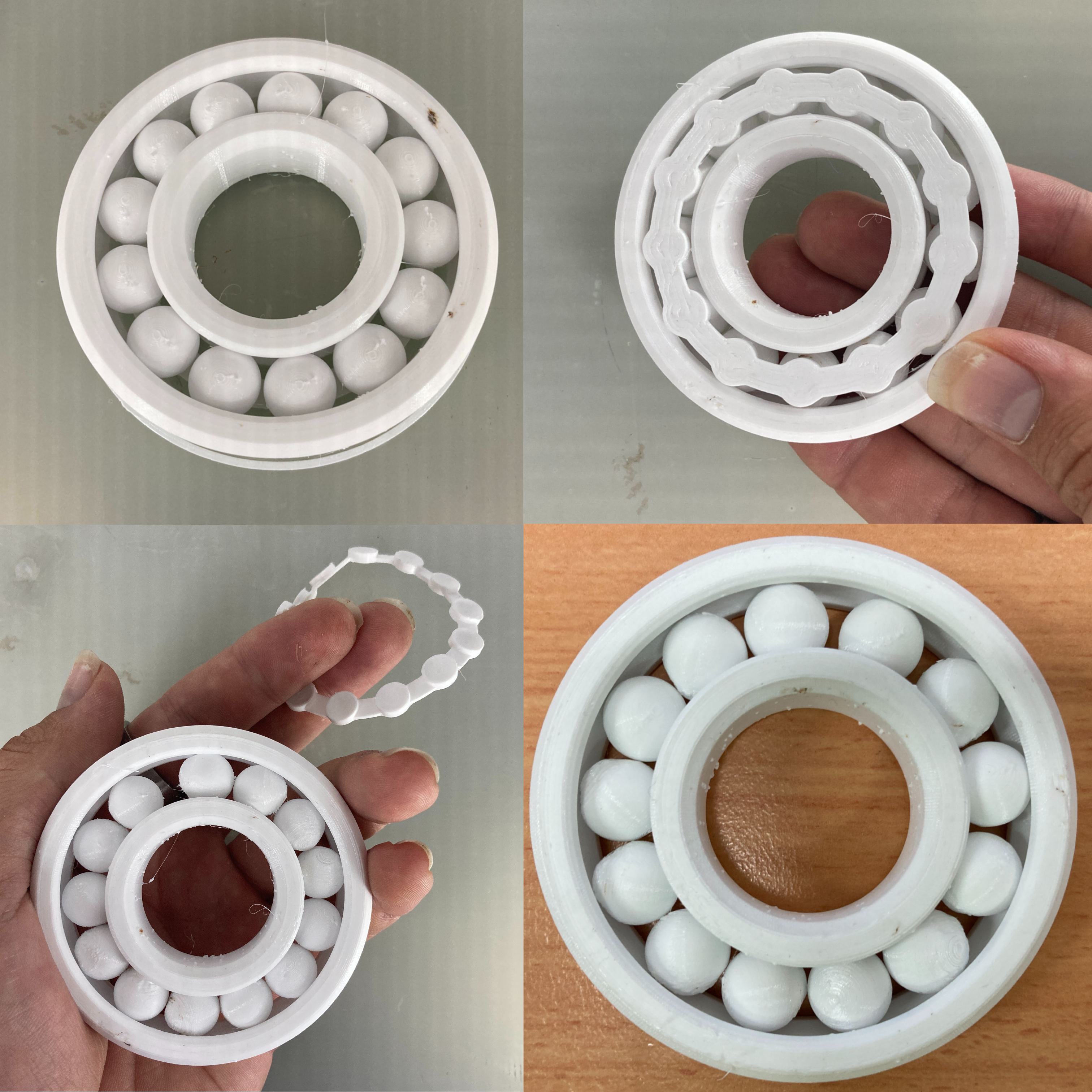
So the goal is to have the same distance between walls as the grail model. We can adjust the Horizontal Expansion setting to achieve exactly this by using the per model setting. This can be found on the left side of Cura and by having the model highlighted (by clicking on it, it will have a blue outline when you do) you will be able to adjust the settings done to it. Make sure to make the setting available to change by clicking Select Setting and then choosing Horizontal Expansion. Then it will show up in the toolbar which you can see in the image below of this happening to the ball bearing. All this means is the value we type here won't affecting the grail model when we slice it. Only the new model will be affected.
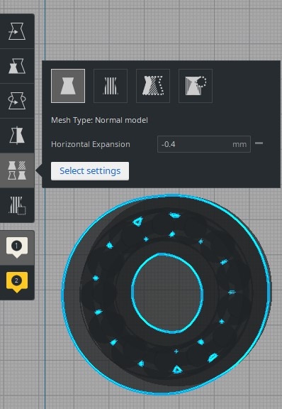
Then we can compare the two models together. Once a similar distance (as judged by a good eye) is achieved you know you can Print-in-Place successfully. Zooming in will help you get the distances exactly right. Then you can remove the holy grail model from the build platform, slice once more and send that file confidently to your 3D printer. See below for a zoomed-in comparison of the two Print-in-Place models.
And below you can see the final result. Print-in-Place with a mechanism perfect first go. Sweet feeling indeed.
Other Settings Worth Nailing
When it comes to Print-and-Place mechanisms often an important is great bridging values. To achieve this it is all about having your machine dialled in to be able to extrude material horizontally between two raised points. This means if two parts are going to be moving over the top of each other such as the carabiner you can see below to the left, it is really important to have that layer of empty between the separated printed parts. Bridging test is a great mechanism to test if a printed part will be able to bridge (naturally) and they often look like shells, see below right.
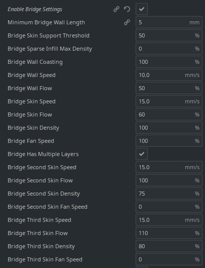
The settings worth considering modifying to improve bridging settings comes down to the fan cooling (increase), print speed (slow down to 30mm/s), nozzle temperature (lower by 2-5 degrees Celsius) and material flow (lower by like 3%). But changing any of these values you are going to alter the print profile. Which means if you have nailed the settings for a particular material and printer changing any of these will mess it all up. But there is a solution! CAD slicers know where sections will be bridging. Thus both Ultimaker Cura and Prusa Slicer provides specific Bridge Settings which you can alter. See below for specifically the bridge settings for Ultimaker Cura.
In Ultimaker Cura the Bridge Settings can be found under the Experimental Settings once enabling All settings to be viewed and then selecting Enable Bridge Settings. These are experimental settings so be ready to dive in deep but this is what you want to alter if you want to improve bridging without messing up your print profile. Doing this will, in fact, further enhance your print profile. Worth remembering some materials are pro-bridging and some are anti-bridging inherently due to their properties. CPE can be challenging to bridge whereas PLA materials with infused carbon fibre particles (or material like CFPEEK) really have their bridging capabilities increase. (Side Note: This is one of my recent discoveries that changed the way I view carbon fibre particle embedded materials. Initially, I had considered it a gimmick, as the carbon fibre particles do not function like long strands of carbon fibre and in fact, lowers the overall strength properties of the material. Little did I know the purpose of the carbon fibre particles is to actually improve the ease of printing, requiring less tinkering to produce really nice end components. Carbon fibre particles will cause the extruding nozzle to wear out faster.)


