Welcome to the Raspberry Pi Pico Workshop, where you will learn everything you need to know to hit the ground running and start making your own projects with the Raspberry Pi Pico and MicroPython. This workshop is designed for complete beginners and teaches a wide range of related skills through bite-size videos. My name is Jaryd, I'm an engineer and also a passionate maker who loves to teach and produce educational videos. This course attempts to be one of the most comprehensive Pico courses for beginners, teaching not only fundamental skills in microcontrollers, coding, and electronics but also the wisdom and insights from many of the folks here at Core Electronics who helped create this course.
To follow along, you will need of course a Raspberry Pi Pico, as well as a few other bits and pieces.
To follow along up to Chapters 2 and 3, you will need to grab a:
All these components can be found here.
As discussed in Chapters 4 and 5, some additional components are needed to follow along with. However, these additional parts can vary depending on your needs and what you wish to do. We have the list of optional parts under those relevant chapters.
Course Outline:
- 1.1 Introduction
- 1.2 What is a Microcontroller?
- 1.3 The Pico Variants
- 1.4 Board Walkthrough
- 1.5 Powering the Pico and Safety
- 1.6 Thonny, Installing Micropython and Hello World
- 1.7 Course Tips
Chapter 2: Pico Basics and Basic IO
- 2.1 Introduction to Basic IO
- 2.2 Digital Outputs and Micropython Basics
- 2.3 Introduction to Breadboarding and Circuits
- 2.4 Reading Digital Inputs
- 2.5 Variables
- 2.6 Reading Analog Inputs
- 2.7 Writing PWM Outputs
- 2.8 Importing Libraries
- 2.9 Running the Pico Without a Computer
- 2.10 Sourcing Power from the Pico
Chapter 3: Logic and Decision-Making
- 3.1 Introduction to Logic and Decision-Making
- 3.2 Boolean Logic and Comparative Operators
- 3.3 If, Else and Elif
- 3.4 For Loops and Lists
- 3.5 While Loops, Breaks and Continues
- 3.6 Functions and Global Variables
Chapter 1: First Steps
1.1 Getting Started
Although this is a video-based course, for each video we will usually have a short text-based rundown or recap of important topics covered in the video, as well as sample code and links to any additional resources. For example:
In this chapter, we are taking it easy and just covering some important beginner topics including:
- What is a microcontroller? (spoiler alert, the Pico is a microcontroller!)
- A walkthrough of the Pico and its Variants
- How to safely use the Pico
- Getting a computer ready to program the Pico
- Some tips on how to get the most out of this course
Let's get started!
1.2 What is a Microcontroller?
In this course, we will be learning how to use the Raspberry Pi Pico, an inexpensive, small, and powerful microcontroller board. Microcontrollers are a kind of small and extremely specialised computer that we can program to complete a specific task, a task that usually involves plugging in hardware like LEDs, buttons, and motors.
If we compared a microcontroller to a regular computer like a desktop or laptop, we would see that a microcontroller is:
- Smaller and lighter.
- Slower, but uses MUCH less power.
- MUCH cheaper.
- Doesn't use an operating system like Windows or Mac, and instead is pre-programmed for a specific task.
These traits mean that microcontrollers like our Pico are more suitable for applications like in an electric toothbrush. We can use a computer to turn on the vibration motor when we press the button. A full-size computer is most definitely overkill, but a microcontroller is perfect. You will find microcontrollers in everything including; drones, washing machines, printers, fans, microwaves, and alarm clocks, they are in an incredible amount of things.
1.3 The Pico Variants
There are 4 variants of the Raspberry Pi Pico to choose from, and they are all very similar with some slight differences.
- Pico: This is the regular "base mode" pico. All Pico variants run the same processor, RAM, and memory as this one. The other variants only add things to this model.
- Pico W: This model comes with wireless capabilities allowing you to connect it to the internet through WiFi, and allows you to use Bluetooth. In nearly every other way it is identical to the regular Pico.
- Pico H: This board is identical to the regular Pico, it just comes with pin headers already soldered onto the board. You will need these headers, and this is just an option if you don't wish to solder your own.
- Pico WH: This board is identical to the Pico W, with wireless capabilities and all. It's just an option that comes with the pin headers already soldered to the board, so if you don't wish to solder them yourself, grab the "H" variant of it.
Any Pico can be used for this course as long as you have the headers soldered onto it. Just be aware that in chapter 5 we learn about the wireless capabilities of the Pico, and you will need a W or WH to follow along with.
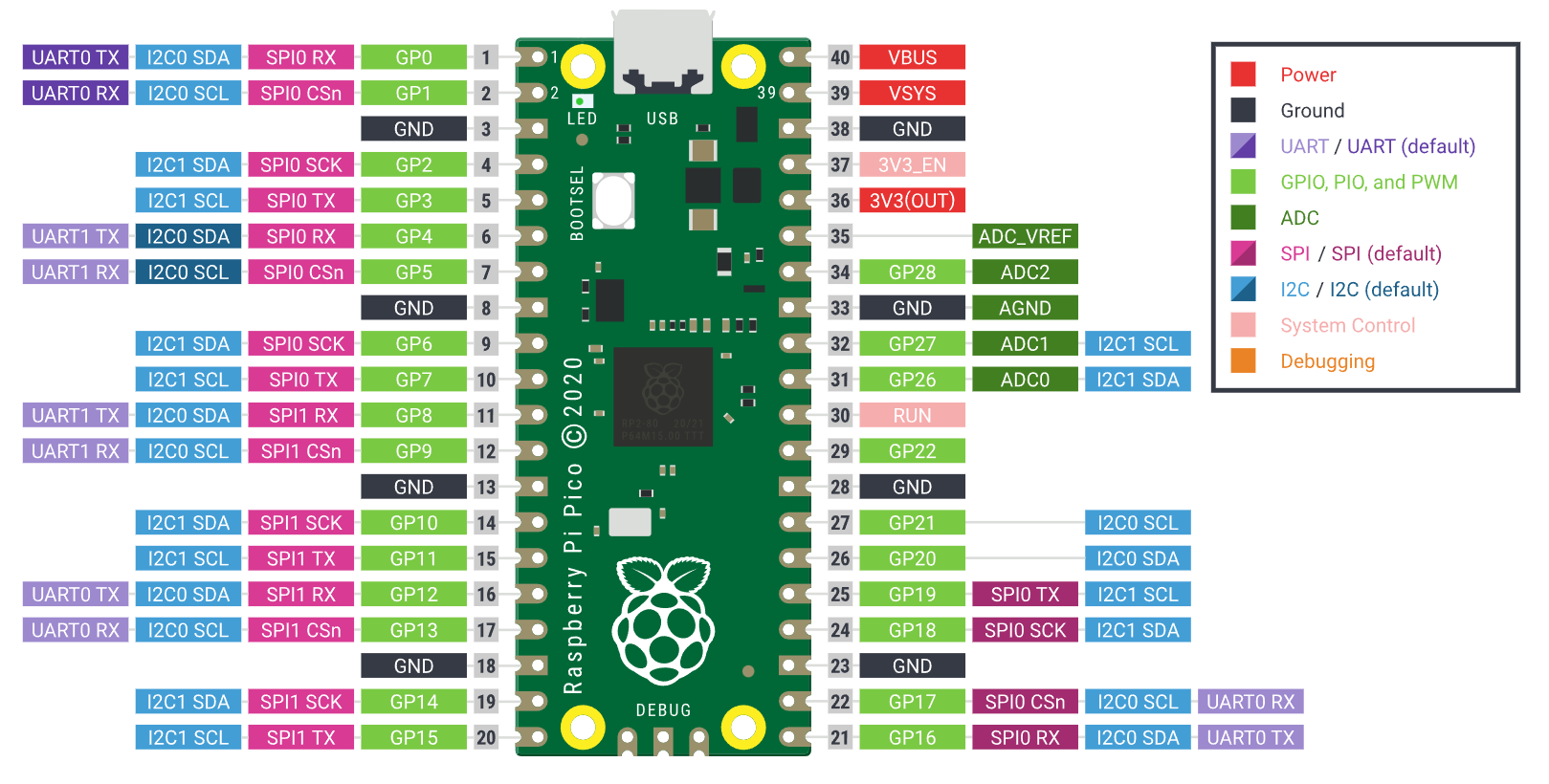
1.4 Board Walkthrough & Pinout
Here is a handy reference diagram for the Pico Pinout. This is the full diagram that has more labels on each pin than just the GP label (these extra pin labels show what else each pin can be used for, we will explore this later).
Right now, the only thing you need to worry about finding are the light green GP pin labels (GP0 - GP28), VBUS, 3V3OUT, and the ground (GND) pins.
If you want some more technical specs for the Pico, you can find them on the Official Raspberry Pi site, where you can also find some other technical resources.
1.5 Powering The Pico & Safety
It is possible to damage your Pico if you don't handle it properly, and the 3 biggest things ways to prevent this are to:
- Unplug the Pico's USB cable before connecting anything to it.
- Double-check that your wiring is correct before plugging the Pico back in.
- Be careful not to accidentally short its pins together, watch out for metal benches!
If you ever power on a Pico circuit and find that your Pico gets very hot in a matter of seconds (too hot to touch), immediately unplug the USB cable and check your wiring, there is most likely something wrong.
1.6 Thonny, Installing MicroPython & Hello World
We're finally going to get into writing some code for our Pico. We will be using Thonny which is a software program that provides tools for coding, editing, and debugging programs.
You can download Thonny from Thonny.org.
After installing MicroPython you will be able to use our first command of the course, the print function which looks like this:
print("Hello, World!")
This function will print whatever is placed inside the brackets, and to print a word or sentence it needs to be placed inside quotation marks. We will be frequently using this print function as it allows us to print important information to the shell, information like sensor data, whether a button has been pressed and important values.
(Also if you have completed this video, you are now in the loop on a programming tradition.)
1.7 Tips For Success
Here are 5 things to know going into this course to get the most out of it.
- Understanding is more important than remembering.
- There is no correct way to do something, some ways may be better, but the best way is the one you are familiar and confident with.
- Learn at your own pace.
- Following along with examples is a great way to learn. The best way though is to experiment and play around with the examples.
- If you get stuck go back to a point it worked (or the beginning) and rework from there, or find an expert to help out.
ChatGPT is a very helpful resource for getting help (even the free version), although you will need to create an account to access it. You can speak to it in plain English, just give it a little bit of context about your issue, and paste in your code if needed.
If all else fails, we have a forum page dedicated to this course where you can ask for help (you can also find it at the very bottom of this page).
Chapter 2: Pico Basics and Basic IO
2.1 Introduction To Basic IO
In this chapter, we will start plugging things into our Pico and writing some code to control them. We will be covering:
- Digital inputs and outputs
- Analog inputs and PWM Signals
- MicroPython Basics
- Breadboarding and basic circuitry
- Basic electrical theory
2.2 Digital Outputs & MicroPython Basics
All 26 GPIO pins on the Pico can act as a digital output (as well as the onboard LED), and we can use this to set the voltage on a pin to be either 0 Volts or 3.3 Volts - this is known as 3.3 Volt logic. The states of these pins can also be called LOW and HIGH, or OFF and ON, or 0 and 1, it all describes whether the signal is 0 or 3.3 volts.
In this first example, we set up the onboard LED as a digital output (setting 3.3 Volts on the LED will turn it on), then using sleeps, we make the LED flash in a pattern. Here is the sample code for that:
from machine import Pin # Import pin from the machine library
import time # Import time library which lets us use the sleep command

led = Pin("LED", Pin.OUT) # Set up the onboard LED (can replace "LED" with a pin GPIO number)

while True:  # Loop forever
    led.value(1)  # Turn the LED ON
    time.sleep(2) # Go to sleep for 2 seconds

    led.value(0)  # Turn the LED OFF
    time.sleep(2) # Go to sleep for 2 seconds
2.3 Introduction To Breadboarding & Circuits
Breadboards provide a quick and easy way to build temporary circuits without the need for soldering. The Pico and other components are placed on the breadboard, and jumper wires are used to connect these components. We will wire up an LED, button and potentiometer, which will be used in the examples for the rest of chapters 2 and 3.
Here is the wiring diagram of that to replicate:

Some important reminders:
- Always ensure that your Pico is unplugged and your circuit is unpowered before you build or modify it
- Double-check that your wiring is correct before plugging your Pico in, and that jumper wires are plugged into the right pins
- Ensure that components are fully inserted into the board, a loose connection is a likely culprit of a circuit that doesn't work
2.4 Reading Digital Inputs
All 26 GPIO pins on the Pico can act as a digital input. When we set up a pin as one, we can think of it acting as a multimeter that will return a value of 0 if the Voltage is close to 0 Volts, and 1 if the Voltage is close to 3.3 Volts.
In this first example, we set up Pin 15 as a digital input (which has a button connected to it), then simply print the result of reading that input. Here is the code for that:
from machine import Pin
import time

# set up pin 15 as an input with a pull-down resistor
button = Pin(15, Pin.IN, Pin.PULL_DOWN)


while True:
    print(button.value()) # read the digital state of the button pin and then print it to shell
    time.sleep(0.1) # without this sleep you may run into issue, it just slows it down a little
We can then combine this with the digital ouput we just learnt to make a simple program that represents the essential function of a micrcontroller. This program takes in an input (the button), does some "thinking" with the if and else functions, then controls and output (an LED) based on that "thinking":
from machine import Pin
import time

# set up pin 15 as an input with a pull-down resistor
button = Pin(15, Pin.IN, Pin.PULL_DOWN)
# set up pin 16 connected to the LED as an output
led = Pin(16, Pin.OUT)


while True:
    # if the button is pressed, then turn on the LED
    if button.value() == 1:
        led.value(1)

    # if its not pressed, then turn the LED off
    else:
        led.value(0)
2.5 Variables
Variables are one of the most essential tools to learn in coding and nearly every program you write from now on will most likely use them. Variables come in different types and the 3 most common are:
- Integers which can store whole numbers like 1, 50, and 8342
- Floats which can store numbers with decimal points like 1.04, 3.14159, and 2451.1024. You can also store whole numbers like integers.
- Strings which can store words and sentences (which must be in quotation marks) like "Hello, World!" and "This is a test sentence that can be stored in a string"
In this sample code, count how many seconds a button has been pressed. To do so, we create a variable called "timer" and update it depending on the state of the button:
from machine import Pin
import time

# set up pin 15 as an input to read our button's state
button = Pin(15, Pin.IN, Pin.PULL_DOWN)

# intialising a timer variable we will use to keep track of time
timer = 0

while True:
    # this ensures that we check the button every second
    time.sleep(1)

    # if the button is pressed, then increase the timer by 1 second
    if button.value() == 1:
        timer = timer + 1

    # print the variable timer to the shell
    print(timer)
There are some rules on what you can name a variable though:
- They must only contain letters, numbers and underscores
- They must start with a letter or underscore and NOT a number
- They cannot be called any of the MicroPython keywords like "import", "while" or "from".
2.6 Reading Analog Inputs
On the Pico, only GPIO pins 26, 27, and 28 can be configured as analog inputs. This is because analog inputs are many times more complex than their digital counterparts and require the use of the Pico's onboard Analog to Digital Converter (ADC).
However, analog inputs are incredibly powerful as they allow your pins to essentially act as a Voltmeter and read the exact voltage on the pin as long as it is between 0 and 3.3 Volts. This isn't what an analog input in MicroPython reads at natively though as it will read that voltage range as a number between 0 and 65,535.
That's why in this sample code where we read and print the voltage on pin 26 (connected to a potentiometer), we use the conversion_factor variable to turn it into a nice readable 0 to 3.3 Volts:
from machine import Pin, ADC # we need to import ADC to use analog inputs
import time

# set up pin 26 as an analog input
pot = ADC(Pin(26))

# constant to convert the 0 - 65535 range to 0 - 3.3 volts
conversion_factor = 3.3 / 65535

while True:
    # read analog input and store it in a variable called pot_voltage
    pot_voltage = pot.read_u16()

    # print pot_voltage
    print(pot_voltage)
    time.sleep(0.1)
2.7 Writing PWM Outputs
Like the overwhelming majority of computers, the Pico is a digital device (a device that deals with 1s and 0s) and while they have little issues with digital signals, they often struggle with analog signals. The Pico requires an ADC just to read analog signals, but like nearly all microcontrollers, it isn't capable of producing a true analog output.
This is where PWM comes to the rescue, by turning the pin off and on extremely fast (thousands to millions of times a second), we can create an average voltage on the pin. The percentage of time the pin is on is called the duty cycle. 50% duty cycle would give 50% of 3.3 Volts, 20% would give 20% of 3.3 Volts and so on. An incredible thing about the Pico is that all 26 GPIO pins can be used to create a PWM signal - with many microcontrollers, you would be lucky to get more than 10.
In this example, we have the simplest implementation and just set a PWM on pin 16 to control the brightness of the LED:
from machine import Pin, PWM # we need to import PWM to use PWM
# intialise pin 16 as a PWM output
pwm_pin = PWM(Pin(16))
# this sets up the frequency that the pin is turned off and on (it is not duty cycle)
pwm_pin.freq(1000)

# this varaible is used to help calculate the required input from a duty cycle percentage
max = 65535

while True:
    # here we multiply max by the desired duty cycle (as a decimal), 0.2 is 20%, 0.7 is 70% and so on
    PWM_value = int(0.5 * max)
    # this line is the command that actually sets the duty cycle
    pwm_pin.duty_u16(PWM_value)
Then we take it up a notch and read the potentiometer with an analog input, and then use that input to control the brightness of the LED in realtime:
from machine import Pin, ADC, PWM
import time
# set up pin 26 as an analog input, and pin 16 as PWM output
pot_pin = ADC(Pin(26))
pwm_pin = PWM(Pin(16))
# set the pin frequency (this is not duty cycle)
pwm_pin.freq(1000)

while True:
    # read the potentiometer value (0 to 65,535) and store it in a variable
    pot_value = pot_pin.read_u16()
    # set the reading as a PWM duty cycle
    pwm_pin.duty_u16(pot_value)

    # uncomment the line below to print voltage instead of the RAW ADC value.
    #pot_value = pot_value * 3.3 / 65535

    print(pot_value)
    time.sleep(0.05)
2.8 Importing Libraries
Libraries are pre-written chunks of code that allow us to achieve a lot with only a few lines of code. For example, when we set up a pin as an analog input, there are quite a lot of things that need to happen to initialise the pin, turn on the ADC, and get the ADC to work with the pin. Thankfully MicroPython comes with the machine library which lets us do all this with a single line of code.
MicroPython comes by default with the machine library, and this is called a "standard library". But there are also external libraries that we can use to achieve specific tasks. One of these examples is the servo library which easily allows us to control a servo by directly specifying an angle (instead of a PWM and having to set the right frequency.)
If you want to explore libraries more or want to make your code experience a little easier, check out the Pico Zero Library, it's a beginner-friendly library made by Raspberry Pi themselves and simplifies the process of using a lot of basic components.
2.9 Running a Pico Without a Computer
It's good and all to run the Pico off a computer, but most projects will probably need to run without it. To achieve this we will need to do 2 things: run the code off our Pico instead of the computer, and power the Pico from another power source.
Running the code off of the Pico is easy enough, save the script you want to run as "main.py" and the Pico will run that file whenever it is powered on.
There are many ways to power the Pico. You can power it through USB (which may be the easiest) using a wall phone charger, battery bank, or AA battery to a micro USB box.
You can also power it through the Vsys pin by supplying 1.8 to 5.5 volts to it. This could come in the form of a small solar panel, some AA batteries, or a LiPo battery.
IMPORTANT: You cannot power the Pico through Vsys and micro USB at the same time, this will most likely damage the Pico and your power source. If you are using Vsys to power your Pico, it is recommended to use a Diode. This only allows electricity to flow in 1 direction, meaning you can safely power your Pico with Vsys and micro USB. BUT ONLY IF YOU HAVE THE DIODE INSTALLED.
2.10 Sourcing Power from the Pico
We arrive at the final video to wrap off chapter 2. This is a mightily practical one as powering components off of your Pico is vitally important as it is very easy to damage something. There are 3 main power sources from the Pico to use:
- 3V3(OUT): This supplies 3 Volts and up to 300 Milliamps of current.
- Vbus: This supplies 5 Volts and up to 2000 Milliamps of current. The current however is dependent on the output capabilities of the USB you are powering it with. If you are using a USB power source that can only supply 1000 Milliamps, you can only use 1000 Milliamps.
- Gpio Pins: These can supply 0 to 3.3 Volts and up to 12 Milliamps of current. You shouldn't try to power many things off the pins besides passive components that need to (such as LEDs and Piezo buzzers).
If you have a device you wish to power, you must match the voltage, and ensure that the power source can supply enough current. For example, a small 9g servo needs 5 Volts and up to 600 Milliamps of power. Vbus matches the voltage of 5 Volts and can supply more than the 600 Milliamps required
Wanna take your power to the next level or interested in using a motor driver? We have a great guide on how to do so.
Chapter 3: Logic and Decision-Making
3.1 Introduction to Logic and Decision Making
In this chapter, we will start adding some "intelligence" to our scripts by learning how to use:
- Boolean logic and operators
- If, else and elif
- For and while loops
- Functions
These are powerful tools that we can use to control the flow of our code, for example, we can choose when to run (or not to run) sections of our code or we can keep repeating code till a certain condition is met. With these basic tools, we can build up more and more complex decision-making and logic to give our scripts a sense of "intelligence".
3.2 Boolean Logic & Comparative Operators
Making a decision with code can be boiled down into 2 steps. The first is to make a statement that compares data, and the second is to choose a course of action based on that comparison. This video will cover the first step of that process and later we will be using these statements to make decisions upon. When we construct a statement, the result of it can only be either true or false. This true or false outcome is known as boolean logic.
In constructing statements, we can compare variables, numbers, and data with comparative operators and thankfully there are only 6 that we need to learn:
- Equals to ( == )
- Not equals to ( != )
- Greater than ( > )
- Less than ( < )
- Greater or equal to ( >= )
- Less than or equal to ( <= )
We can use these to construct statements to compare different pieces of data. For example, we could check if x is equal to y, or if a temperature reading is greater than 40, and these will return true or false boolean logic.
We can also construct statements using boolean operators which allow us to compare comparisons, and there are only 3 that we need to learn:
- and - which returns true if statements A and B are true.
- or - which returns true if statement A or B is true.
- not - which can be used to inverse the logic of a statement (makes a true statement return false, and vice versa)
3.3 If, Else, & Elif
Now that we know how to make a statement, lets learn how to execute code based on the result of that statement. 3 powerful tools to do this are the if, else, and elif (else if) keywords.
- If - we give it a statement and a section of code, if the statement is true the code will be executed.
- Else - we place it after an if or elif and give it a section of code, if the if before it is false then the code we place inside of the else will be executed.
- Elif - this behaves like an if check, but the elif will only check its statement when the if or elif before it is false. It is kind of like saying "if the previous if wasn't true, give this one ago.
We can use these keywords to control the flow of our code and make decisions based on data or inputs. In this video's example we use if, elif and else to check the input from a potentiometer and produce a volume output based on it.
from machine import Pin, ADC
import time

pot = ADC(Pin(26))

# set up conversion constant and start a last volume variable at 0
last_volume = 0
const = 100 / 65535

'''
change this string to choose which method is used.
a uses if, else and elif in an inefficient method.
b uses a more efficient method.
'''
method = "b"

if method == "a":

    while True:
        # Read the value from the potentiometer
        current_volume = int(pot.read_u16() * const)

        # Check if the volume level has changed enough to print new line
        if ((current_volume - last_volume) >= 2) or ((current_volume - last_volume) <= -2):

            # use if, elif, else logic to print a volume bar based on the current volume
            if 0 <= current_volume < 10:
                print("__________", current_volume)

            elif 10 <= current_volume < 20:
                print("█_________", current_volume)

            elif 20 <= current_volume < 30:
                print("██________", current_volume)

            elif 30 <= current_volume < 40:
                print("███_______", current_volume)

            elif 40 <= current_volume < 50:
                print("████______", current_volume)

            elif 50 <= current_volume < 60:
                print("█████_____", current_volume)

            elif 60 <= current_volume < 70:
                print("██████____", current_volume)

            elif 70 <= current_volume < 80:
                print("███████___", current_volume)

            elif 80 <= current_volume < 90:
                print("████████__", current_volume)

            elif 90 <= current_volume < 100:
                print("█████████_", current_volume)

            else:
                print("██████████", 100)

            # Update last volume
            last_volume = current_volume

        time.sleep(0.05)  # Small delay to prevent excessive reading


if method == "b":

    while True:
        # Read the value from the potentiometer
        current_volume = int(pot.read_u16() * const)

        # Check if the volume level has changed enough to move to a new 10% increment
        if ((current_volume - last_volume) >= 2) or ((current_volume - last_volume) <= -2):

            # This is a different way to create the volume bar based on volume
            num_bars = int(current_volume / 10)
            print("█" * num_bars + "_" * (10 - num_bars), current_volume)

            # update last volume
            last_volume = current_volume


        time.sleep(0.05)  # Small delay to prevent excessive reading
3.4 For Loops & Lists
For loops are one of the two types of loops we can use in MicroPython (and most coding languages as well). For loops are designed to be looped a set and known amount of times, and they will execute the code placed inside of them on every loop.
In this example, we use for loops to create a servo sweep with the servo library (the same one we used in chapter 2.8). This script slowly rotates the servo in a smooth motion from 0 to 180 degrees then back. Like in this example, the range function is often used with for loops to set the number of times it is looped.
from machine import Pin, PWM
from time import sleep
from servo import Servo

# Initialize Servo on pin 0 with micropythonservo library
servo = Servo(pin_id=0)

# Sweep the servo from 0 to 180 degrees and back
while True:
    for angle in range(0, 180, 5):  # start at 0 and count in 5s until 180 is reached

        # angle will be updated every loop so we will use it to set the servo angle
        servo.write(angle)
        sleep(0.1)

    for angle in range(180, 0, -5):  # 180 to 0 degrees, 5 degrees at a time

        # angle will be updated every loop so we will use it to set the servo angle
        servo.write(angle)
        sleep(0.1)
Another powerful tool that can be used with for loops is lists which is a sequence of variables put together. For example, here is a list of floats, integers and strings with a for loop looping through them.
test_list = [12, 447, 1344, 134, 234.23, "hello"]

for i in test_list:
    print(i)
This script will print out all the elements of integers, floats and strings from that list in order. Lists can be used with for loops like this to loop over strings or custom number sequences that would be impossible to make with the range function.
3.5 While Loops, Breaks, & Continues
While loops are the other type of loop we can use and they utilise the boolean logic statements we constructed before. Whilst for loops are designed to loop a set and a known amount of times, while loops will keep continuously looping a section of code until the statement we give it returns false. An example of this is that we might use it to keep checking the temperature until it equals 40 degrees.
We have already been using while loops with the main while true loop in our scripts. In that instance, we directly feed it the TRUE boolean logic which will keep it looping forever.
In this example, we create a reaction tester game and wait for a button press with while loops. We also use a handy function called tick_ms, which can be called to get the time in milliseconds since the board was powered on, and we use it to measure the passing of time.
from machine import Pin, Timer
import time
import random

button = Pin(15, Pin.IN, Pin.PULL_DOWN)  # Initialise button
led = Pin(16, Pin.OUT)                 # Initialise LED

while True:
    print("Press the button to start the game.")

    # reset button state
    button_state = 0

    # this while loop waits until the button is pressed
    while button_state == 0:
        button_state = button.value()


    print("Ready?")
    # Wait for a random time
    time.sleep(random.randint(2, 5))  # Wait for 2 to 5 seconds randomly

    # Turn on the LED
    led.value(1)

    # Start measuring reaction time from tick_ms
    start_time = time.ticks_ms()

    # reset button state
    button_state = 0

    # wait for the button to be pressed again
    while button_state == 0:
        button_state = button.value()

    # Calculate reaction time
    reaction_time = time.ticks_ms() - start_time

    # Turn off the LED
    led.value(0)

    print("Your reaction time is:",reaction_time, "milliseconds")

    # Add a small delay before the next round starts
    time.sleep(1)
2 other really handy functions to know are continue and break, which can be used with both while and for loops. They are a little bit situational, but having them in your maker toolbox is vitally important.
- The break function can be called inside of a loop and when it does, the while or for loop will immediately finish and move on to the code after the loop.
- The continue function can also be called inside of the loop and when it does, the loop will end its current iteration and move onto the next cycle of the loop.
These can be used to effectively put a stop to loops or to skip certain cycles in loops.
3.6 Functions & Global Variables
While functions technically aren't a part of logic and decision-making, they complement this idea well as they can be used to easily control the flow of code.
Functions are a way to store a section of code in a nice and self-contained section of our script. We give that section of code a name, and then we can run that code by calling that name. This means that functions are great in managing code that needs to be repeated multiple times as we can just call it repeatedly.
Functions don't have to just be a list of instructions as we can also pass information into the function, and pull information out of it. This can be used for example to take in numbers, perform calculations on it, and return an answer.
When using functions, something to be careful of is global and local variables. When we create a variable in a function it is known as a local variable and will ONLY exist inside of that function. When the function ends... the variable ends. If we create a variable outside of a function, this is called a global variable and these are the variables we are used to dealing with. We can access global variables inside of a function as well.
Here is an example of functions in use, we use them to create a moving average filter to smooth out some sensor noise. Pay careful attention to the use of local and global variables, as well as how information is passed in and out of functions.
from machine import ADC, Pin
import time

# Initialize the ADC for the potentiometer
pot = ADC(Pin(26))

    # thie function reads potentiometer, assigns it to current reading, then shifts all the readings in the window by 1.
def update_window():
    global current_reading, last_reading1, last_reading2, last_reading3, last_reading4

    last_reading4 = last_reading3
    last_reading3 = last_reading2
    last_reading2 = last_reading1
    last_reading1 = current_reading
    current_reading = pot.read_u16()


    # takes in 5 numbers and calculates the average of them
def calculate_average(val1, val2, val3, val4, val5):
    # calculate the average of the 4 numbers
    total = val1 + val2 + val3 + val4 + val5
    average = total / 5
    return average


# Initialize variables for current and the last 4 readings
current_reading = pot.read_u16()
last_reading1 = pot.read_u16()
last_reading2 = pot.read_u16()
last_reading3 = pot.read_u16()
last_reading4 = pot.read_u16()

while True:

    # Update readings
    update_window()

    # Calculate moving average
    moving_avg = calculate_average(current_reading, last_reading1, last_reading2, last_reading3, last_reading4)

    # Print the moving average
    print("Raw Data:", current_reading, "Moving average:", moving_avg)

    # Wait before the next reading
    time.sleep(0.1)  # Adjust the delay as needed
This is just one example of using functions and although this code could be easily written without the use of them, functions make it easier to read as our while true loop is less cluttered. The code doesn't technically need functions, it just makes life easier for us humans.
Chapter 4: Advanced IO
4.1 Introduction to Advanced IO
Now we start to get into the cool stuff. With basic IO we were reading sensor data by interpreting voltage levels, but with advanced IO, our sensors now instead send that data by rapidly changing the voltages on their pins to strings of information.
This system of communication is called a com protocol, which is just a set of rules or a standard that devices can use to communicate data. The pico has native support for 3 protocols, UART, SPI and I2C, all of which will be explored in this chapter.
With com protocols, we start using a lot of things called modules. Modules are just self-contained sensors or devices that take in power, and when connected to the pico via a com protocol, provide information. When we use a module with a com protocol, it will send information to the pico in strings or numbers directly, instead of trying to interpret voltages (like with an analog temperature sensor).
These modules are often extremely library-dependent, meaning that every device will have a different library and chunk of code to use them. This means that this chapter becomes a little harder to follow along with without having the same hardware we use in the examples. If you wish to follow along you'll need another Pico for UART, a micro SD card reader for SPI, and an OLED and atmospheric sensor for the I2C video. If you have your own hardware using these com protocols it is still possible to follow along with the videos outside of the coding section. However, if there is one thing I could recommend following along with, it would be using the OLED screen in the I2C video as it is an incredibly powerful addition to any project.
4.2 UART
UART or Universal Asynchronous Receiver Transmitter, is one of the most commonly used communication protocols out there thanks to its simplicity and robustness. It allows 2 devices to talk to each other over 2 wires, 1 for sending data, and 1 for receiving it. This allows you to connect a Pico to other devices including UART modules like this GPS, computers like a Raspberry Pi 5, and other microcontrollers like an Arduino or another Pico, which we will be going through as an example in this video.
Using UART is incredibly easy in a MicroPython Environment as we don't need any external libraries and can send and receive data with simple commands. In the sample code below we send data from one Pico (Pico A), by first setting up an instance of UART, and then using the .write() function to send string data.
from machine import UART, Pin # we need to import UART to use it
import time

# Initialize UART 1 on Pico A, TX pin is GP4 and RX pin is GP5
test_uart = UART(1, baudrate=9600, tx=Pin(4), rx=Pin(5))

while True:
    test_uart.write('ON')  # Send 'ON' message to Pico B
    time.sleep(2)      # Wait for 2 seconds

    test_uart.write('OFF') # Send 'OFF' message to Pico B
    time.sleep(2)      # Wait for 2 seconds
Then on our second Pico (Pico B), we receive the messages with the .read() function, and then use if checks to compare the received string to control the onboard LED.
from machine import UART, Pin

# Initialize UART 1 on Pico B, TX pin is GP4 and RX pin is GP5
test_uart2 = UART(1, baudrate=9600, tx=Pin(4), rx=Pin(5))

# set up onboard LED
led = Pin("LED", Pin.OUT)

while True:
    # Check if anything is available in buffer
    if test_uart2.any():

        # recieve and store the message in a variable
        message = test_uart2.read().decode() # this .decode() removes the byte string format
        print(message)

        # control the led based on the string
        if message == "ON":
            led.value(1)

        elif message == "OFF":
            led.value(0)
Although UART is nice and simple, there are a few things to watch out for. When reading in data on the pico, it's often a good idea to check the buffer which holds incoming data while it's waiting to be received. This is done with the .any() function inside the if statement which returns true when something is in the buffer. Another function used is .decode() which removes the byte string format which is just a by-product of using UART, remove it and see this funky format if you want. Another thing to keep in mind is that you can only send strings in a MicroPython environment, so if you wish to send an integer, you must first convert it to a string with str().
And finally, the most important thing to remember about UART is that you MUST CONNECT RX TO TX AND TX TO RX. This is because if one pico transmits data, you want to receive it on the other. This is something that trips up even seasoned makers.
4.3 SPI
SPI or Serial Peripheral Interface, is a blazingly fast com protocol that allows us to connect multiple devices together and have them all communicating with each other at once. However, having multiple devices connected at once is a little complex and there is a management system called controller/target architecture. You may have heard the master/slave terminology used, but this is being phased out. However, a new standard is yet to be properly established so you may hear many other names used
Regardless, it all works the same with the controller (the Pico in our case) managing and conducting all the communications, and the target devices (sensors and modules) follow these directions. To do this, SPI uses 4 wires, a shared clock wire to keep all these interactions in sync, a wire for the controller to send data to the target devices, a wire for the target devices to send data to the controller, and a chip select wire (although you may need more than one) which is used by the controller to talk to the targets.
SPI is a very fast protocol, whilst UART typically runs at a baud rate in the 100's of thousands at the higher end, SPI can have a baud rate into the 10s of millions. This means that it is great in applications that require high data transfer rates. In this example, we utilise this ability by using an SD card adapter module to perform some basic data logging.
This was adapted from our Makerverse SD card guide if you want to take a look.
Here is a link to the library (you can right-click and hit save link as to download it).
from machine import SPI, Pin, ADC
import sdcard, uos
import time
import random

# Here we intialise our SPI peripheral, and then send it off to the library to use
spi = SPI(1,sck=Pin(14), mosi=Pin(15), miso=Pin(12))
cs = Pin(13)
sd = sdcard.SDCard(spi, cs)

# Here we mount the SD card so that our Pico can see it
uos.mount(sd, '/sd')
print(uos.listdir('/sd'))

print("Starting ADC samples")

# Open a text file on the sd card, then generate a number and write it to the file
with open('/sd/adcData.txt', "w") as f:
    while True:
        x = random.randint(0, 100)
        f.write(str(x)) # Write sample data
        f.write('\n') # A new line
        f.flush() # Force writing of buffered data to the SD card
        print(x)
        time.sleep_ms(500)
As great as SPI is, it lies in a bit of a niche. If we were to connect a pico to another microcontroller or computer, it may be wise to opt for UART due to its simplicity and robustness. Although many SPI sensor modules exist, if we were to connect several of them together, it may be easier to use I2C. So you'll often find SPI playing to its strength of its high speeds in applications like this camera module, e-ink displays, and higher resolution OLED displays.
4.4 I2C
I2C or Inter-Integrated Circuit, is an incredible protocol that has the ability to connect over 100 devices with only 2 wires! 1 wire is dedicated to a clock to keep everything in sync, and another is for data to be sent along. Like SPI, it achieves this with the controller/target terminology to carefully manage the flow of information along this single data wire.
I2C devices are also incredibly easy to use. You connect the SCL (clock) pin of the device to the SCL pin of the Pico, and the SDA (data) pin to the Pico's SDA pin. Any additional devices you wish to connect will follow the same rules. In this video, we go through an example of this by connecting up an I2C OLED display and an atmospheric sensor to the same pins of a Pico.
If you are following along with the same hardware, you will need this OLED library, the atmospheric sensor library, as well as the additional unified library for it (and you can also visit the documentation page for more sample code).
import ssd1306
import time
from machine import Pin, I2C
from PiicoDev_BME280 import PiicoDev_BME280


# Initialize I2C perhipheral
i2c = I2C(0, scl=Pin(9), sda=Pin(8), freq=400000)

# Initialise OLED display
oled = ssd1306.SSD1306_I2C(128, 64, i2c, addr=0x3c)

# Initialise Atmospheric Sensor
sensor = PiicoDev_BME280() # initialise the sensor

while True:
    tempC, presPa, humRH = sensor.values() # read all data from the sensor

    # Clear OLED display (this wont take effect till we .show())
    oled.fill(0)

    # Display our text and variables, the right 2 numbers are the x and y coordinates of the text
    oled.text("Temp:", 5, 10)
    oled.text(str(tempC), 60, 10)
    oled.text("Press:", 5, 30)
    oled.text(str(presPa), 60, 30)
    oled.text("Humid:", 5, 50)
    oled.text(str(humRH), 60, 50)

    # Push changes to the display
    oled.show()
One of the issues with connecting many I2C devices is dealing with address conflicts. Addresses are used in I2C to keep track of who is currently sending data, so every address on an I2C bus must be unique. The problem lies in that addresses are hardware-based and 2 of the same devices will share the same address from the factory. You may be lucky and find switches on your device that can be used to change its address, or you may need to resolder a resistor. What ever is possible, its always a good idea to plan out address conflicts in the planning stage of your project.
Chapter 5: Pico W, Wireless and Webpages
5.1 Introduction to Wireless Capabilities
The wireless abilities of the Pico are possibly the coolest thing that this microcontroller can do as it opens up a world of Internet of Things-related applications. We are no longer bound by having data stored locally and we can now send and receive data through networks. This allows us to take projects to the next level. A weather station becomes a smart weather station that can beam that data over Wi-Fi, an alarm clock can now track wake-up times and graph that to be viewed on other devices, and a pico-powered light display can now be controlled through a phone. While there are many methods we can use to achieve these things, we will be learning how to do so using web pages being served by the pico.
Each video in this chapter compounds onto the next one and can almost be treated as one long video. We will start by connecting the Pico to a Wi-Fi network, then querying some sites over the internet to collect some data, then we will host a web page that we can interact with to control the Pico's hardware, then we will learn how to set up the Pico to host its own Wi-Fi that we can serve that page over, and finally, we will take a look at adding some more advanced functionalities to our web page.
While this may sound a little daunting, much of the heavy lifting is done by libraries making this whole process incredibly streamlined.
And a final note before we get into it, this chapter is building to an end goal: a template that we can use to serve a webpage over a wireless network to control the Pico with. We will be making the skeleton for this that can be modified and applied to your projects. Let's get into it!
5.2 Connecting to the Internet
Let's start with the most important step of all this - connecting a Pico to a wireless local-area network (WLAN). There isn't much to this, but we thought it would be a good opportunity to explore another capability of the Pico, connecting to the internet. This isn't going to allow you to watch YouTube or even load a single image (the thumbnail of a YouTube video will fill half the Pico's RAM), instead, it will allow us to query sites that return us useful text data. Let's take a look at how it does that with this sample code:
import network
import time
import urequests

# set up some variables with our wifi details, replace these with your Wi-Fi credentials
ssid = "my-wifi"
password = "Password1"

# this function connects the pico to a wifi network
def connect():
    #Sets up wireless module instance, turn on the wireless hardware, and then connect with our credentials
    wlan = network.WLAN(network.STA_IF)
    wlan.active(True)
    wlan.connect(ssid, password)
    # We print the status of the connection here to help see whats going on
    while wlan.isconnected() == False:
        print("Connecting, please wait...")
        time.sleep(1)
    # Once it completes the while true loop, we will print out the Pico's IP on the network
    print("Connected! IP = ", wlan.ifconfig()[0])

# The Pico will Try to connect to a site, and if it runs into an error, will run the except code
try:
    connect()
    # define the site we want to try to connect to
    site = "http://worldtimeapi.org/api/ip"
    print("Querying: ", site)
    # Query the site and store it in r, then we convert it from a JSON string
    r = urequests.get(site)
    print(r.json())
    r.close()

except OSError as e:
    # and if it fails, we will close the connection and let us know in the shell.
    r.close()
    print("Error: connection closed")
We are using a few good house-keeping things in this code:
- Try and Except: These are used for error handling and function simply - the Pico will try what is in the try section and if it runs into an error, it will run what's in the except section. With the possibilities of unsuccessful connections and other network-related issues, these are vital for keeping your Pico from crashing and coming to a standstill.
- Prints Statements: Much of this connecting and querying sites isn't visible to us humans. By using print statements to let us know what the Pico is currently doing it is both easier to develop and use. If you have a project that uses wireless capabilities, it may be a good idea to print these wireless interactions out on an OLED display.
- Functions: This sort of code can get very messy very quickly and by grouping code into a callable function (like the connect() function), we keep everything clean and easy to work with. It also makes it easier to adapt to other projects as we can now just copy the connect() function and paste it into any other project to get the pico to connect to a wireless network.
And that is how we can connect the Pico to the internet and this is incredible when you think about it. With a few dozen lines of code, we can get our inexpensive microcontroller to connect to a server halfway across the globe and collect live data. In this example, we queried the time and date, but there are many other sites that may be helpful for your projects:
- Position of the ISS: http://api.open-notify.org/iss-now.json
- Fun number facts: http://numbersapi.com/random
- Random cat fact: https://catfact.ninja/fact
- Random zen quotes: https://zenquotes.io/api/random
- Earthquakes detected by the USGS in the last hour: https://earthquake.usgs.gov/earthquakes/feed/v1.0/summary/all_hour.geojson
- Realtime currency exchange rates: https://api.exchangerate-api.com/v4/latest/USD
- Random dad jokes https://icanhazdadjoke.com/slack
5.3 Hosting a Wi-Fi Access Point & Web Page
Now we know how to connect the Pico to a wireless network, let's create a method of interacting and controlling it. For this, we will be using web pages as they are easy to create, simple to use and allow us to build what we want from the ground up.
There are 3 steps we will need for this. First, we will need to allow clients (other devices using a web browser in our case) to connect to the Pico; for this, we will be using sockets. Once they are connected we will need to serve them a web page to interact with; we can write a simple web page with HTML, CSS and Javascript that may present the client with buttons, sensor data, or whatever we want. And finally, when a client interacts with the page, they will send a request back to the Pico. This request will contain information about what the client did (e.g. what button they pressed), and we will use this request to control the Pico, in this case, we will be controlling the onboard LED.
Here is the code that we build in the video to achieve that:
import network
import socket
import time
from machine import Pin, ADC

# set up onboard led
led = Pin("LED", Pin.OUT)

state = "OFF"

# set up some variables with our wifi details, replace these with your Wi-Fi credentials
ssid = "my-wifi"
password = "Password1"

# this function connects the pico to a wifi network
def connect():
    #Sets up wireless module instance, turn on the wireless hardware, and then connect with our credentials
    wlan = network.WLAN(network.STA_IF)
    wlan.active(True)
    wlan.connect(ssid, password)
    # We print the status of the connection here to help see whats going on
    while wlan.isconnected() == False:
        print("Connecting, please wait...")
        time.sleep(1)
    # Once it completes the while true loop, we will print out the Pico's IP on the network
    print("Connected! ip = ", wlan.ifconfig()[0])

# you can call this function to make the pico host its own wifi AP instead
def ap_setup():
    # Sets up wireless module instance, configures access point, then turns on Wi-Fi hardware
    ap = network.WLAN(network.AP_IF)
    ap.config(ssid=ssid, password=password)
    ap.active(True)
    # We print the status of the connection here to help see whats going on
    while ap.active() == False:
        print("Initialising access point...")
        time.sleep(1)

    # Once it completes the while true loop, we will print out the Pico's IP on the network, will default to 192.168.4.1
    print("AP is operational, ip = ", ap.ifconfig()[0])

# function to open a socket which is what the pico uses to allow other devices to send and recieve information with.
def open_socket():
    # gets adress information for the socket, create a socket, bind it, then start listening for any clients trying to connect
    address = socket.getaddrinfo('0.0.0.0', 80)[0][-1]
    s = socket.socket()
    s.bind(address)
    s.listen(1)
    # then we will return this socket so we can use it in our main section
    return (s)

# This defines the webpage to be served.
def webpage(state):
    html = f"""
            <!DOCTYPE html>
            <html>
            <form action="./on">
            <input type="submit" value="Turn Light on" />
            </form>
            <form action="./off">
            <input type="submit" value="Turn Light off" />
            </form>
            <p>LED state: {state}</p>
            </body>
            </html>
            """
    # return the webpage as a string so we can serve it in our main section
    return str(html)

# start by either hosting ap or connecting to Wi-Fi
connect()
#ap_setup()
# and then open the socket
s = open_socket()

try:
    # this loop ensures the page is served everytime a client connects, not just once.
    while True:
        # this is a blocking call, the code will stop here until a client tries to connect
        client = s.accept()[0]
        # when a client does connect, it will send a request which we will store in a variable
        request = client.recv(1024)
        request = str(request)
        # this request comes through as a giant mess, this part gives us just /request?
        try:
            request = request.split()[1]
        # the pass is important because we cannot always split a request, this will prevent errors
        except IndexError:
            pass
        print(request)

        # here we use comparative logic to control the LED based on the request
        if request == "/on?":
            led.value(1)
            state = "ON"
        elif request =="/off?":
            led.value(0)
            state = "OFF"
        # then we recreate the html site with the updated states
        html = webpage(state)
        # This sends a http response header back to our client, some browsers might not work without this line. very technical.
        client.send("HTTP/1.1 200 OK\r\nContent-type: text/html\r\n\r\n")
        client.send(html)
        # end by closing the client, will reopen again next loop.
        client.close()

# if we get an error, we will close the connection and let us know there was an error.
except OSError as e:
    client.close()
    print("Error: connection closed")
And with this, most of our template is complete. Something else this code has is the function ap_setup() which we can call instead of connect() to make the Pico host its own Wi-Fi network we can connect to. There are pros and cons of this, but it is a powerful tool to have the Pico host its own AP as we don't need to rely on being in a place with an existing network. It is also far more reliable and easier to test code with and when developing any web page on the Pico, it may be a good idea to test it in AP mode and switch it over to the connect() function when needed.
An important thing worth pointing out here is that this set-up only allows us to connect to the Pico with a client on the same wireless network; meaning that you cannot connect to this web page through the internet. Although this can be achieved with port-forwarding, this opens up a can of worms relating to network security issues as you are allowing anyone from the open internet into your home network. If you wish to access the Pico via the internet, we recommend using a service like the Things Network or Adafruit IO which we have a guide on setting up with the Pico. Although these services won't allow you to serve webpages like we are doing so here, you can reach the same project goals using them and after this chapter will have adequate knowledge on how to set them up.
5.4 Improving Web Page Functionality
We have the "infrastructure" that we can use to serve a webpage and handle requests that come back and now we can add functionality in whatever way we want to this. To add something, there are 2 key places we need to change; the webpage and the while true loop. First, we need to serve this addition on the webpage, if we are sending data we need to print that data, and if we intend on controlling something, we need to add an input element on our page. Then we need to modify the relevant section in the while true loop; if we are sending data to the webpage, we need to update that data (e.g. we might read a sensor), and if we are adding an input, we need to handle the new requests from that element.
Below is our final template, feel free to copy and paste it into future projects, and note that we have added a few things in this video. We have first added code that measures the onboard temperature sensor and sends it to the page, an example of reading a sensor and displaying it. We have also added a slider input which controls a PWM output on pin 16. The request for this slider needs to be managed as it comes in the form /slider1?slidervalue. We split this request into the 2 parts that compose it, the path and parameters with the path being "/slider1", and the parameter being "slidervalue". In the following tabs, you will also find other helpful code that we mention in the video.
The final point of this chapter is that this is a microphone course, not an HTML course so we may not be able to write nice code for our web page. In this case, a Large Language Model like Chatgpt may be incredibly helpful in helping develop and teach code for the web page.
import network
import socket
import time
from machine import Pin, ADC, PWM

# set up onboard led, temp sensor and pin 16 as a PWM
led = Pin("LED", Pin.OUT)
temp_sensor = ADC(4)
pwm_pin = PWM(Pin(16))

state = "OFF"

# set up some variables with our wifi details, replace these with your Wi-Fi credentials
ssid = "my-wifi"
password = "Password1"

# this function turns the temp sensor ADC value into degrees celcius
def read_temperature():
    conversion_factor = 3.3 / (65535)
    reading = temp_sensor.read_u16() * conversion_factor
    temperature = 27 - (reading - 0.706) / 0.001721

    return temperature

# this function connects the pico to a wifi network
def connect():
    #Sets up wireless module instance, turn on the wireless hardware, and then connect with our credentials
    wlan = network.WLAN(network.STA_IF)
    wlan.active(True)
    wlan.connect(ssid, password)
    # We print the status of the connection here to help see whats going on
    while wlan.isconnected() == False:
        print("Connecting, please wait...")
        time.sleep(1)
    # Once it completes the while true loop, we will print out the Pico's IP on the network
    print("Connected! ip = ", wlan.ifconfig()[0])

# you can call this function to make the pico host its own wifi AP instead
def ap_setup():
    # Sets up wireless module instance, configures access point, then turns on Wi-Fi hardware
    ap = network.WLAN(network.AP_IF)
    ap.config(ssid=ssid, password=password)
    ap.active(True)
    # We print the status of the connection here to help see whats going on
    while ap.active() == False:
        print("Initialising access point...")
        time.sleep(1)

    # Once it completes the while true loop, we will print out the Pico's IP on the network, will default to 192.168.4.1
    print("AP is operational, ip = ", ap.ifconfig()[0])

# function to open a socket which is what the pico uses to allow other devices to send and recieve information with.
def open_socket():
    # gets adress information for the socket, create a socket, bind it, then start listening for any clients trying to connect
    address = socket.getaddrinfo('0.0.0.0', 80)[0][-1]
    s = socket.socket()
    s.bind(address)
    s.listen(1)
    # then we will return this socket so we can use it in our main section
    return (s)

# This defines the webpage to be served.
def webpage(state, temperature):
    html = f"""
            @lt!DOCTYPE html@gt
            @lthtml@gt
            @ltbody@gt
            @ltform action="./on"@gt
            @ltinput type="submit" value="Turn Light on" /@gt
            @lt/form@gt
            @ltform action="./off"@gt
            @ltinput type="submit" value="Turn Light off" /@gt
            @lt/form@gt
            @ltp@gtLED state: {state}@lt/p@gt
            @ltp@gtTemperature: {temperature}@lt/p@gt
            @ltinput id="slider" type="range" min="0" max="100" onchange="updateSlider(this.value);"@gt
            @lt/body@gt
            @lt/html@gt
            """
    # return the webpage as a string so we can serve it in our main section
    return str(html)

# start by either hosting ap or connecting to Wi-Fi
#connect()
ap_setup()
# and then open the socket
s = open_socket()

try:
    # this loop ensures the page is served everytime a client connects, not just once.
    while True:
        # this is a blocking call, the code will stop here until a client tries to connect
        client = s.accept()[0]
        # when a client does connect, it will send a request which we will store in a variable
        request = client.recv(1024)
        request = str(request)
        # here we assign path and request to a value incase the request cant be split
        path = "empty"
        parameters = "empty"

        # this tries extracts the request and splits it into its path and parameters
        try:
            request = request.split()[1]
            path, parameter = request.split("?")
            print(path, parameter)
        except:
            pass

        # here we use comparative logic to control the LED based on the PATH, not the request now
        if path == "/on":
            led.value(1)
            state = "ON"
        elif path == "/off":
            led.value(0)
            state = "OFF"

        # If the slider is changed it will have the path /slider1, we will then set the pwm to the parameter
        elif path == "/slider1":
            pwm = int(int(parameter) * 65535 / 100)
            pwm_pin.duty_u16(pwm)
            print(pwm)

        # update the temperature to send to the webpage
        temperature = read_temperature()
        # then we recreate the html site with the updated states
        html = webpage(state,temperature)
        # This sends a http response header back to our client, some browsers might not work without this line. very technical.
        client.send("HTTP/1.1 200 OK\r\nContent-type: text/html\r\n\r\n")
        client.send(html)
        # end by closing the client, will reopen again next loop.
        client.close()

# if we get an error, we will close the connection and let us know there was an error.
except OSError as e:
    client.close()
    print("Error: connection closed")
This is an element that can be pasted into a webpage to create a slider. This is the simplest slider possible and is short and sweet, all fitting in 1 line.
@ltinput type="range" min="0" max="100" value="50" onchange="window.location.href = '/slider1?' + this.value "@gt
This is a function that takes in the ADC reading of the onboard temperature sensor and converts it into degrees celsius.
# this function turns the temp sensor ADC value into degrees celcius
def read_temperature():
    conversion_factor = 3.3 / (65535)
    reading = temp_sensor.read_u16() * conversion_factor
    temperature = 27 - (reading - 0.706) / 0.001721

    return temperature
Chapter 6: Where to From Here?
6.1 MicroPython You Need to Know
Outside of the main topics in the chapters, there is a whole heap of helpful MicroPython functions that can be a lifesaver in projects - and we have tried to weave some of these in along the way, but some were maybe a little too complicated to introduce.
That's why before we wrap it up we are going to go over these just so you are aware of them. We aren't going to dive into them in great detail, just enough to get you going. Don't feel like you need to master these right away, the objective of this video is to make you aware of these and what they do so they can sit in your toolbox and you can revisit them when you need to.
I'd also like to add one more great resource, this Pico reference sheet from micropython.org that contains examples of much of what we have covered in this course all in 1 convenient place.
We have already covered ticks_ms in our while loops video, but it's worth visiting again because it is so vitally important. ticks_ms is a function that we can call that measures the time since the pico has been turned on and we can use it as a reference point to measure something time-wise. Here is some sample code below that sleeps the pico for a random time and measures how long that sleep was with ticks_ms.
Hint: tick_ms is a great tool for debugging if you want to see how long a certain chunk of code takes to run (if you ever run into processing speed issues).
import time #tick_ms is in the time library
import random

# start by measuring the current time since the pico was powered
start = time.ticks_ms()

# sleep the board by a random time
time.sleep(random.random())

# take the current time since pico turned on, minus the time measured before
# and you will measure how long the random sleep was
elapsed_time = time.ticks_ms() - start

print(elapsed_time)
Previously when we have been checking if a button has been pressed we have been checking it in a while true loop. Now this method does work but if our loop has a sleep and the button is pressed during that sleep, then it won't be detected; this is where interrupts can help. A good analogy is checking if a parcel has been delivered to your house. The while true loop method is like checking the front door every minute or so to see if the package has been delivered which is terribly inefficient. What if instead we added a doorbell and let the delivery person ring it when the package has arrived - this is an external interrupt.
The following code sets up a button on pin 15 () to act as an interrupt. The code has a while true loop that prints "Hello" every 2 seconds and pressing the button will interrupt this while true loop and toggle the onboard LED.
from machine import Pin
import time

# set up our button and LED like we normally do
button = Pin(15, Pin.IN, Pin.PULL_DOWN)
led = Pin("LED", Pin.OUT)

# define a function that we will call when the button is pressed
def button_handler(pin):
    led.toggle()

# set up the interrupt on the button we made, assign the function to be called
button.irq(trigger=Pin.IRQ_RISING, handler=button_handler)

# Here we print hello every 2 seconds normally, and we should be able to
# press the button which will run the code regardless of whats happening here
while True:
    print("Hello")
    time.sleep(2)  # sleep for 2 seconds
An issue that arises when we read the button presses with an interrupt is that it may be pressed multiple times. This is because of the nature of buttons that they will rapidly change between on and off even if we press them once. To fix this we can use tick_ms to measure the passing of time since the last press and only press the button if enough time has passed. Here is the same interrupt code but modified to do this:
from machine import Pin, Timer
import time

# set up our button and LED like we normally do
button = Pin(15, Pin.IN, Pin.PULL_DOWN)
led = Pin("LED", Pin.OUT)

# this variable will keep track of the last time the button was pressed
last_button_press_time = 0

# define a function that will be called when the button is pressed
def button_handler(pin):
    # tell python we want to use the global variable, not create a local one
    global last_button_press_time

    # get the current time
    current_time = time.ticks_ms()

    # only toggle the LED if 80 ms has passed since last toggle
    # this ticks_diff is another way of calculating the passing of time
    if (time.ticks_ms()- last_button_press_time) > 80:
        led.toggle()
        last_button_press_time = current_time

# set up the interrupt on the button we made, assign the function to be called
button.irq(trigger=Pin.IRQ_RISING, handler=button_handler)

# Here we print hello every 2 seconds normally, and we should be able to
# press the button which will run the code regardless of whats happening
while True:
    print("Hello")
    time.sleep(2)  # sleep for 2 seconds
Another form of interrupts we can use are timer interrupts. These behave the same as external interrupts but instead of using GPIO pins to trigger the interrupt, they use time. In the following example, we have a regular old while true loop printing "Hello" every 2 seconds, but we also set up 2 timers. One is periodic timer that toggles the onboard LED every second, and the other is a timer that runs once after 5 seconds have passed.
This is an extremely powerful ability as it allows us to run code at precise timings. A great application of this would be in checking sensor data on a fixed time period.
from machine import Pin, Timer
import time

# set up our LED as normal
led = Pin("LED", Pin.OUT)

# set up our two timers
toggle_timer = Timer()
five_second_timer = Timer()

# define the functions we will call in each timer
def toggle_led(t):
    led.toggle()

def five_seconds(t):
    print("5 seconds have passed")

# define a PERIODIC timer, this one will run every 1000 ms
toggle_timer.init(mode=Timer.PERIODIC, period=1000, callback=toggle_led)

# define a ONE_SHOT timer, this one will run ONCE after 5000 ms has passed
five_second_timer.init(mode=Timer.ONE_SHOT, period=5000, callback=five_seconds)

# Here we print hello every 2 seconds normally, and this will run alongside our timers
while True:
    print("Hello")
    time.sleep(2)
Asyncio is one of the most powerful things that you can learn in MicroPython as it unlocks an entire world of parallel tasks. Whilst timers can be used to have two lots of tasks running at once, a far more robust way to do this is using Asyncio as it allows you to have multiple while true loops running at the same time.
There is a little bit of weird structuring and set-up required to start an Asyncio process, but it's just different - not difficult. In the following example, we set up two processes, one is a while true loop that prints hello every 2 seconds, and the other toggles the LED every second:
from machine import Pin
import uasyncio as asyncio # importing it with this name makes it easier to use
import time

led = Pin("LED", Pin.OUT)

# define the while true loop you wish to use inside of a function
async def print_loop():
   while True:
       print("Hello")
       await asyncio.sleep(2)

# this is our other while true loop we will be running
async def blink_loop(led):
    while True:
        led.toggle()
        await asyncio.sleep(1)

# start by creating an asyncio loop event
loop = asyncio.get_event_loop()

# bind the tasks to the loop event (assign the functions)
loop.create_task(blink_loop(led))
loop.create_task(print_loop())

# start the asyncio events
loop.run_forever()
PIO or Programmable Input Output is a bit of a step up in terms of complexity and is a feature unique to the rp2040. PIO lets you write very precise code to interact with the GPIO pins in a very efficient and responsive manner as it has its own dedicated processing unit and hardware. One of the coolest applications of this is in creating your own custom communication protocols. The Pico doesn't support CanBus natively, but with PIO you can add your own. The Pico only has 2 UART peripherals, but with PIO you can program your own and add more. Have an obscure protocol from a 90s arcade machine? PIO can be used to interface with it.
There are many more things you can do with PIO and although it is a little complex, it isn't wildly difficult and it can be a lifesaver when you need timely and precise GPIO interactions. Here is a really simple example of using PIO to toggle the onboard LED. This is not a very good use of PIO, but it demonstrates it in an accessible manner. If you want to learn more about PIO we have a great example of it in action of controlling Neopixels, and there is also this amazing community creation with lots of PIO examples.
import time
import rp2
from machine import Pin

# in this function we assign the PIO function
@rp2.asm_pio(set_init=rp2.PIO.OUT_LOW)
def blink():
    wrap_target() # this wrap_target signals the start point of a loop
    set(pins, 1)   [31] # we set the pin to 1 (on), then we wait for 31 cycles
    nop()          [31] # which is denoted by the [31]. Each instruction in PIO
    nop()          [31] # can have 32 cycles. This nop() does no operation for 1
    nop()          [31] # cycle, then we wait another 31. This is how we "sleep" in PIO
    set(pins, 0)   [31] # then we turn the pin off, and wait for another set of cycles.
    nop()          [31]
    nop()          [31] # This whole loop has 8x32 (256) cycles.
    nop()          [31]
    wrap() # and this wrap signals the end point of the loop

# start the statemachine and assign the blink function to it as well as the pins
# we also tell it at what frequency to run at. Our PIO function has 256 cycles per loop
# so at a frequency of 2560 it will run 10 times a second. The minimum freq is 2000.
sm = rp2.StateMachine(0, blink, freq=2560, set_base=Pin(16))

sm.active(1)
time.sleep(5)
sm.active(0)
A few other non-MicoPython things worth mentioning. First of all, the Pico can also be programmed in C++. There are times that this might be useful as C++ is more lean and efficient, but for most projects it isn't warranted. However if you ever find yourself in need of venturing into the world of C++, don't be too scared as once you learn one language, its really easy to transfer over to another.
The other thing is that there are more rp2040 boards than just the Pico. The Pico is the official board, but the Raspberry Pi foundation sells the rp2040 chip and other companies purchase them to make their own specialised boards, often with unique quirks. Take a look at this list of rp2040 boards and you may find some cool stuff you wouldn't of thought about.
6.2 Where to Now?
This is it, the final section, congratulations for reaching this point and we genuinely mean it.
First of all, I want to take a moment on behalf of the entire team at Core Electronics to again congratulate you for finishing this course. We spend a great deal of our time to get these resources produced and seeing people use them and learning from them is what we want in the end.
We have covered quite a lot in this course and we think it's safe to say that you can now no longer consider yourself a beginner but an intermediate maker. But this journey doesn't end with this workshop, this is just the end of the beginning chapter. Now you can start to do the really cool stuff. This course has equipped you with tools and it's now up to you to use them and add more to your maker toolbox. The best way is through doing, so find a project. You may have had some ideas throughout this course, but if you are ever seeking inspiration here are a few good sources:
- Our community projects page is where we have gathered some of the cool and whacky projects.
- Youtube is another source of inspiration for projects.
- The blog Hackaday collects some of the coolest projects from around the internet
- Make is the original maker's magazine and again has cool projects from around the net.
There are also many other powerful tools to add to your toolbox like 3d printing, laser cutting and circuit board making and we have an entire other course on these essential maker skills. If you ever need a hand with your maker project or you just want to share something you have made, we have a community forum full of a wonderful bunch of makers who are over there doing the same.
Regardless of what you choose to do, we here at Core Electronics wish you and your projects the best of luck!

