Being punctual is important. Hence accurate time is required. Clocks tend to miss out when it comes to accuracy especially when they are set by the user. So, why not get accurate time from the internet and use tried and tested hardware to maintain the time instead?
MATERIALS REQUIRED
OPTIONAL PARTS
- 3D Printed enclosure
- Mechanical screws, headers
- Adhesives
TOOLS REQUIRED
I must admit, I am not as punctual as I should be, and many people are in the same boat as I am. I often blame it on my clock being a few minutes fast/slow which has become a regular excuse. I am not a huge fan of it as I am sure many are not as well. When it comes to setting the time on all of the mechanical clocks at home, I tend to do it manually which adds error since no human can easily set the time accurately. And that error is annoying.
Now my solution to fixing this problem is simple. Internet time is accurate 99% of the time. Don’t trust me? The clock on your computer which is set with internet time is what the majority of people use and it is very accurate (until the RAM battery runs out, of course.)
So, I chose to get the setup time from the internet and then continue maintaining it with an RTC, which is extremely accurate. This eliminates the human error factor. And that is exactly what I want.
I started the prototyping process with an ESP8266 NodeMCU board which is used in multiple hobbyist projects. It is easy to use, comes with 2.4 GHz Wi-Fi capabilities and also works with the Wi-Fi Manager library which is something I shall explain more about further in the article.
The breadboard is the prototyper's friend. It helps prototype fast and easy. That is how the first prototype was made and tested. Now, you the reader, don’t have to go through the hardships of prototyping and also realising how important reading datasheets is; since I have finished that task which you can easily replicate. So, this upcoming part is just to illustrate in words and pictures the amount of work that has been put in.
The MCU was first placed on the breadboard and the LCD and DS1307 were hooked up based on their pinouts. The SCL and SDA pins were connected together and the project was tested by modifying the example codes for the LCD and the DS1307. Now, I hoped it would work and my thinking behind the same was that the LCD and the RTC do not have conflicting I2C addresses. Also, the working voltage range is the same. But that was not the case.


Any common man might give up. I am no common man. I am the lazy man who began this project, so I walked off and thought about it for a while and chose to peek into the datasheet. Now, the circuit was not completely broken. It worked, but not as expected.
Looking into the Serial Monitor, I confirmed that the RTC was refusing to increment the time. Now this is an issue that is not documented. This was primarily because of the fact that the solution is mentioned in the datasheet itself. However, being a super smart hobbyist, chose to ignore it.
Pictured Right: The serial monitor prints out the current status of the time, and the fact that it is not changing every three seconds while showing the wrong set time, shows that the circuit has a fault
The datasheet mentions that a crystal oscillator of a frequency of 32.768KHz is a must to keep the RTC running accurately. Since I neglected the fact, the RTC refused to increment the time accurately.

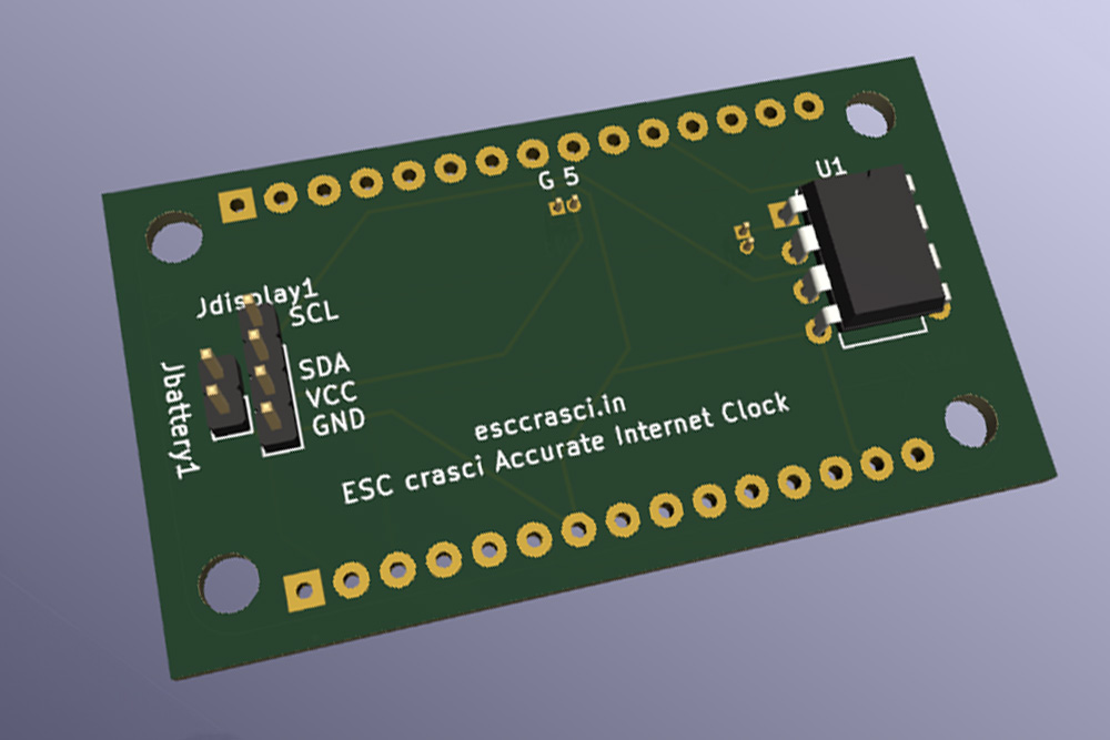
One night without finishing the prototyping on the breadboard, I decided that I must order the PCBs for this project with many other projects and did not add headers for the oscillator. This became an easy fix that could have been easily averted, and the final schematic and PCB also reflect it. I also did not perform the DRC (Design rule check) and made the mistake of connecting the SDA to VCC while placing the nets which was not an easy fix. But nothing is impossible in this lab. Anyhow, the final PCB file has that issue fixed. I also made the mistake of not adding sufficient markers on the main PCB. This is not an issue, but a guideline that makes final assembly easy. I fixed this in the final file as well.
Now the above paragraph obviously indicates that a schematic was prepared and a PCB was routed. This usually marks the end of the prototyping stage. However, because of the faults, the PCB became a part of the prototyping process.
After I received the PCBs I realised my mistakes, and spent over a week just finding faults and mistakes. Don’t do what I did and maybe save a lot of time in the process,
Since I received the PCBs, I started assembling and realised my mistakes. As I found them, I fixed them in the original schematic as well. Because re-ordering would be expensive, I botched the errors with wire-wrapping and 24 gauge wire. And with that, the PCB was done too.


After I finally got it to work, I started working on the case. Mind you, the code was not fully complete. But since I work faster doing hardware projects, I finished the enclosure first.
This is the most important part of a project. Its aesthetics! Even if the project is impeccable, yet it does not look the part, people will not look at it. To combat this issue, I chose some contrasting colours and designed a simple 3D case in TinkerCAD, a free CAD software. The proactive TP4056 hole was added to enable easy powering up of the project.
I printed the case out with my ENDER 3 with the help of CHEP’s modified high-speed Print Profile. However, I would highly recommend the standard slicer profile CURA offers for the Ender 3 since I feel the output quality will be much better. You can make a wooden case, provided you have the time and resources. I am lazy and just chose to move on with the print.
The case itself is 3D Printed with PLA in DUAL-TONE (Fancy!) in White and Blue which goes well, according to me.

THE CODE
During the first stages of prototyping, I did not use the internet function. Instead, I just made the clock work with the MCU alone. I highly recommend that you do the same to prove that the connections are correct. It will save a lot of time as it did for me as well.
#include "RTClib.h" #includeLiquidCrystal_I2C lcd(0x27,16,2); RTC_DS1307 rtc; char daysOfTheWeek[7][12] = {"Sunday", "Monday", "Tuesday", "Wednesday", "Thursday", "Friday", "Saturday"}; void setup () { Serial.begin(57600); lcd.init(); lcd.clear(); lcd.backlight(); #ifndef ESP8266 while (!Serial); #endif if (! rtc.begin()) { Serial.println("Couldn't find RTC"); Serial.flush(); while (1) delay(10); } if (! rtc.isrunning()) { Serial.println("RTC is NOT running, let's set the time!"); rtc.adjust(DateTime(F(__DATE__), F(__TIME__))); } } void loop () { DateTime now = rtc.now(); //UNCOMMENT BELOW CODE TO TEST RTC ALONE //Serial.print(now.year(), DEC); //Serial.print('/'); //Serial.print(now.month(), DEC); //Serial.print('/'); //Serial.print(now.day(), DEC); //Serial.print(" ("); //Serial.print(daysOfTheWeek[now.dayOfTheWeek()]); //Serial.print(") "); //Serial.print(now.hour(), DEC); //Serial.print(':'); //Serial.print(now.minute(), DEC); //Serial.print(':'); //Serial.print(now.second(), DEC); //Serial.println(); lcd.setCursor(4,0); lcd.print(now.hour(), DEC); lcd.setCursor(6,0); lcd.print(':'); lcd.setCursor(7,0); lcd.print(now.minute(), DEC); lcd.setCursor(9,0); lcd.print(':'); lcd.setCursor(10,0); lcd.print(now.second(), DEC); delay(3);
I wanted to scrape the time from the worldtimeAPI which is pretty good when it comes to accuracy as I confirmed by checking the time side by side with the NPL Clock (nplindia.in). So, I chose to scrape it and get the time. I did this with the Arduino JSON library and the JSONHttpClient code. I added that URL to the code and made it print the whole string in the serial monitor.
Now we cannot use the complete string since it also has other data including temperature etc. which are unnecessary for this project. So, I sliced the string and assigned it to a new variable to use later. The time came when I had to combine the RTC code and the JSON code. Doing this was easy. But setting the sliced time (x) as the start time of the RTC was not possible since it is still a String and it had to be made into an Integer which I did with the toInt() method.
Pictured Right: The new integer is assigned to a predefined variable in the header of the code. And the use of Serial outputs helps the debugging process.)

Now the hours, minutes, and seconds are once again sliced from the main string, converted to integers, and saved in new variables. These are then assigned to the RTC so that it can start counting by using the rtc.adjust() function. Now I don’t care about the year and hence chose to ignore it. But it is up to you to decide if you want the clock to maintain the day and date as well by adding more variables.
With this, the setup part ends (literally and figuratively). The loop part is simple since it only involves printing the hours, minutes, and seconds on the display. This is achieved with the lcd.print() function and with that the code is almost complete (to a state where it does work).

The WiFi.h library makes it hard to change the network of the device on the fly, so I chose to change it to the WiFI Manager Library by Tzapu so that it makes the users life easier. And hey, it does. It involves a minor change where a few more lines are added and removed. It also includes the WifiManager.h library definition before void setup().
With that, the code is done! Moving on to the boring part of understanding how the code works. The above steps must have given a vague idea regarding its working. But the enthusiasts read on, but I tend to go on directly to the last step, which is finishing the project.
The ESP first connects itself to the internet with the credentials. Then it REQUESTS the JSON file from the URL we provided. Then it scrapes and extracts the time. Finally, it assigns the time to the RTC and it is incremented periodically by the RTC and then displayed on the display.

//Code by Atul Ravi aka ESC crasci 2023-2024 //esccrasci.in #include#include #include #include LiquidCrystal_I2C lcd(0x27,16,2); const String dataURL = "http://worldtimeapi.org/api/timezone/Asia/Kolkata.json"; String x; String hourss; String minss; String secs; int hourint; int minsint; int secsint; void setup() { WiFi.mode(WIFI_STA); WiFiManager wm; wm.resetSettings(); bool res; res = wm.autoConnect("AutoConnectAP","password"); // password protected ap Serial.begin(57600); lcd.init(); lcd.clear(); lcd.backlight(); } void loop() { if(WiFi.status() == WL_CONNECTED) { HTTPClient http; http.begin(dataURL); int httpCode = http.GET(); if(httpCode> 0) { if(httpCode == HTTP_CODE_OK) { String payload = http.getString(); //Getting parts of time x= payload.substring(73,82); hourss = payload.substring(73,76); minss = payload.substring(76,78); secs = payload.substring(79,81); Serial.println (hourss); Serial.println (minss); Serial.println (secs); hourint = hourss.toInt(); minsint = minss.toInt(); secsint = secs.toInt(); //LCD Code lcd.setCursor(4,0); lcd.print(hourint, DEC); lcd.setCursor(6,0); lcd.print(':'); lcd.setCursor(7,0); lcd.print(minsint, DEC); lcd.setCursor(9,0); lcd.print(':'); lcd.setCursor(10,0); lcd.print(secsint, DEC); delay(3); } delay(10); } } }

The final print came out looking good and before I finally fit the PCB in the case, only one final hardware change remained. Adding the TP4056 board. I did this by soldering 2 small wires to the USB output pins of the charging board.
Now you need not use the TP4056. You can use a MicroUSB or Mini USB breakout board provided you find it. But I used the TP4056 since I have many of them in abundance and it is much easier to obtain that than a breakout. But the choice is up to you.
I did the final honors by supergluing the TP4056 to the case base plate. Then I used some hot melt glue and attached the LCD to the case and used 2 screws to fasten the PCB to the base as well. The final step was gluing the base plate to the case. And with that the project was complete!


THE FINISHING REGRETS AND CHANGES
The project was not as easy as I thought and took a major chunk of my time. But the final output came out much better than what I thought it would. It is a device that is going to be on my desk from this day on.
Now some changes that you could make to improve this project:
- You can remake the whole design and make it even more aesthetically pleasing. Maybe wood filament?
- Another change that could be made would be using a different display rather than using the same old 16*2 LCD.
- The final change I would recommend is maybe using a better MCU that will be much more efficient like the Raspberry Pi.
Before I end the article. The code, BOM, and additional pictures are available to download here with the corrected schematic and PCB file and 3D Enclosure STL files as well. Once again, I hope you enjoyed reading this article as I sure did the whole process of making the project and documenting it.

