In this guide, we go over some common ways of adding motion to your project with actuators such as stepper motors, servos and linear actuators, to help you choose which one is most appropriate for your situation.
The start of this guide covers some basic ideas about torque and force, but after that, each actuator type is designed so that it can be read in isolation. E.g. if you want to just learn about stepper motors you can read the beginning paragraphs about torque and forces and then just read the stepper motor section.
Contents:
What is an Actuator?
Put simply, an actuator is a device that produces motion from energy. DC motors, servos, stepper motors, and solenoids are all actuators as they convert electrical energy into movement. Actuators can also be powered by pneumatics (air-related) or hydraulics (fluid-related), but for this guide, we will be sticking with electrical actuators. There is a wide range of electrical actuators to choose from each with their own abilities and limitations, but in general, actuators will produce 2 types of motion; rotational or linear (motion in a straight line). something here about a quick physics lesson.
So let's go over some common actuator types, their pros and cons, the motion that they provide, and how to choose an appropriately sized actuator for the job you need.
Load, Speed and Current
When dealing with actuators, there is an important concept of load, and it refers to a force or weight that an actuator must move or overcome. An example would be an automatic garage door - the heavy door is a load that the motor must lift up against gravity. A remote control car has a load - the weight of the car itself is the load and the car's motors must move this load around.
Another important idea is the relationship between load, speed and current. These are best understood by looking at the 2 extremes that an actuator can be subject to, no-load and stall conditions.
No-load conditions are exactly what the name implies - when an actuator is not moving or "throwing around" very much of a weight or load. Stalling on the other hand is when the actuator is not able to move despite electrical power being applied. This occurs when too large of a load is applied to the actuator and it isn't powerful enough to overcome it.
The graph on the right depicts this mostly linear relationship between speed, load and current. We have pulled this from a DC motor datasheet, with the increasing load on the bottom x-axis. On the far left we have no-load conditions where we will have the greatest speed and least current, and on the far right we have our stall conditions with the lowest speed and greatest current. This graph is for a specific motor and every actuator will have a different maximum load, speed and current.
The key takeaway here is that as we place a greater load on our actuator, it will slow down and draw more current until it reaches its maximum rated load where it will stall.

What is Torque and Force?
Force is force, and torque is just a rotational force.
Well, let's dive a bit deeper into that, but without using too much physics. As mentioned before, actuators can produce either rotational or linear movement and will have a maximum amount of force it can exert in this motion. When dealing with actuators that produce linear motion, you will encounter forces in units like kg-f (kilogram-force) or N (Newtons). In rotational motion, you will encounter rotational forces (torque) in units like kg-cm (kilogram-centimetres) and N-m (Newton-meters).
Force
We can understand rotational force units by first understanding linear force units. Let's take a look at this linear actuator as an example, which has a maximum output force of 13 kg-f (or 128 Newtons). In the world of physics, Newtons are the standard unit of force, but kg-f may be a little easier to understand. (If you hold a 1 kg weight, it will push down on your hand with 1 kg-f of force thanks to gravity.)
This means that if had a set-up like we have in the diagram on the right, where we mounted this linear actuator to a wall, placed a set of scales underneath, then extended the linear actuator and pressed into the scales, we would measure a MAXIMUM of 13 kg on the scales. At this point, the actuator would stall because the absolute maximum force this actuator can apply is 13 kg-f.
It should be noted that this does not mean that it can move a 13 kg object but instead can apply 13 kg of force to an object.
Newtons are another unit of force. Their relationship is through gravity and 1 kg-f = 9.8 N, so 13 kg-f is going to be equal to 128 N. Feel free to use either unit, but it may be easier to convert units to kg-f as we know what a kg of force feels like.

Torque
Now we are ready to discuss torque. Again, let's use a practical example by looking at this Feetech servo, which has a maximum output torque of 10kg-cm. This means that if we attach an arm to the servo, and then rotate the servo into a set of scales, at a distance of 1 cm it will result in a force of 10 kg-f. If we increase the length of this arm and the distance at which we apply this torque at, we decrease the amount of force that is applied. This is best seen in the image on the right
If we make the distance 5 times longer, we can only apply a fifth of the force, and if we make the distance 10 times longer, we can only apply a tenth of the force.
So when using kg-cm, if you want to find out how much torque will be applied at a certain distance, divide the torque by that distance (in centimetres).
N.m is our other common unit of torque, and again it is the standard unit in the world of physics. Torque in this unit works exactly the same, but this time it is a measurement of newtons at a distance of meters. 1 N.m of torque is equal to 10.2 kg-cm, so our 10 kg-cm servo is approximately 1 n.m. (And again it may be beneficial to just convert your units to kg-cm as it may be easier to understand.)

In a similar fashion to the image above, we can not only push down with 10 kg-cm of force but can also lift with 10 kg-cm of force as seen in the diagram on the right. This means that if we place a 1 kg weight at a distance of 10 cm, the servo can apply exactly enough torque to keep it from falling.
However, the reason it isn't moving is that we have perfectly matched the load to the maximum output of the servo and it has stalled. Placing this 1 kg weight at 10 cm creates a load of 10 kg-cm, and as our servo can only output 10 kg-cm of torque we have created these perfect stall conditions. If we had a more powerful servo that could output more than 10 kg-cm, we would be able to lift that load upwards as it can apply more torque than the load we are applying to it.
IMPORTANT: You should try to keep your actuators far away from stall conditions as they can quickly damage and overheat your actuator. Many actuators can be damaged if they are held at stall conditions for even a few seconds.
And that is the end of our venture into a little bit of physics. We tried to keep it light and not dive in too deep, but now we have just enough knowledge of force and torque to have a good understanding of actuators.

Servos
Servos are an extremely popular actuator that produces rotational motion and specialises in precise control of position. They are typically composed of a small DC motor, gearbox, and controller, all enclosed in a housing with a servo horn protruding from the top. They can be set to an exact angle (usually from 0 to 180 degrees) and have an internal feedback system that makes the servo “fight” to keep the angle that it is set to. When dealing with servos, the unit kg-cm is commonly thrown around. This torque unit can be thought of as how much rotational force the servo can apply and “fight” to keep the angle it has been set to.

Characteristics of Servos:
- Precise Position: Servos have an internal feedback mechanism that allows for precise control of position. Not only can you set the servo to an exact angle (and it will move to that same angle every time), but you can precisely control speed (e.g. increase the angle by 0.1 degrees every 1 second).
- Limited Rotation: Servos can typically only be set to an angle of 0 to 180 degrees, sometimes more, sometimes less - it's different for every servo.
- Positional Feedback: Servos always know exactly what position they are in at all times. While stepper motors can also be set to precise angles, they do not know what position they are in. This means that if we place too great of a load on a stepper, it may force the stepper to spin and create a positional error. Because servos always know what position they are in, they automatically adjust back to the correct position.
- Easy Implementation: A servo has 3 wires. 2 for power and a 3rd for a PWM signal to be set on (this is how you control the angle). You don't need to know the exact PWM to set as there are many libraries for every microcontroller that will let you input the angle and it will set the appropriate PWM signal.
A great example of a servo in action is in remote control planes. The image on the right shows a common application of a servo being used to control the elevator of an RC plane. The servo is connected to the hinged elevator with a push rod and as the servo rotates it rotates the elevator to control the plane.
This is a great application because:
- The elevator only needs a limited amount of rotation, well under 180 degrees
- The elevator needs to be set to a precise angle
- The servo packs a decent amount of torque for such little weight
- Aerodynamic forces might overload the servo and create a positional error, but there servo's positional feedback will correct this error

Servo Specifications
There is a wide range of servos to choose from and several key factors to consider when choosing a servo for your application. Let's quickly discuss some important ones:
- Form Factor: Servos come in several form factors, but the 2 most common sizes are standard and micro. Typically, larger servos will have more torque but also require more power and weigh more.
- Operational voltage: You will often see a voltage range that the servo can be powered with (usually from 4.8V to 6V or 8.4V). Any voltage in the listed range will allow the servo to operate, but supplying the servo with the higher Voltage values in this range will result in greater torque and faster rotation speeds.
- No-load Speed: This is the fastest rotational speed the servo is capable of when under no-load conditions. Usually, it is listed as either revolutions per minute (RPM) or seconds / 60 degrees (how many seconds it takes to rotate 60 degrees).
- Current Draw: Most of the time there will be 2 current ratings, stall current and no-load current (sometimes also called the peak and running currents). The no-load current is what you can expect when the servo is under no-load conditions, and the stall rating is the absolute maximum current that the servo can draw when it is stalling. You should always prepare for this stall current and ensure your power supply and circuit can handle this maximum value.
- Torque: You will see either 1 or 2 torques listed. If 1 is listed, it will most likely be the peak torque and this is the maximum torque the servo can be loaded with (remember it will stall at this torque). Running a servo constantly near its peak torque can wear it out, so often there is a second torque rating listed - the continuous torque. This is an amount of torque that the servo can continuously output without overheating or causing damage. If it is not listed, a good rule of thumb is 1/3 of the peak torque.
Continuous Servos
While we have so far discussed positional servos, another variety worth mentioning is the continuous servo (also referred to as rotational servos). Unlike the positional servo, these servos are capable of continuous rotation, functioning similarly to a standard DC motor. This ability is thanks to the removal of the servo's internal feedback mechanism, which unfortunately removes its ability to be set to or regulated to a specific angle.
The key advantage of continuous servos is their simplicity—an inbuilt gearbox and motor driver, all packed into a small device needing only three wires for connection. One of the significant benefits is that the motor can be controlled with just one wire. The control mechanism is straightforward—setting it to 90 degrees halts movement, setting it to 0 degrees moves it at full speed in one direction, and 180 degrees drives it at full speed in the opposite direction. This makes them an easy-to-use and compact motor and gearbox that is well suited for projects like small lightweight cars.
DC Motors
DC motors are another extremely common actuator. They generate internal magnetic fields to produce continuous rotational motion and are one of the simplest actuators available. DC motors typically have no positional knowledge or feedback system and just spin freely and continuously.
Characteristics of DC Motors:
- Simplicity and Cost: DC motors are typically more straightforward and cheaper than stepper and servo motors as they have a simpler construction and do not require complex control systems. This lack of complexity leads to a less costly motor that is easier to implement in basic rotating applications.
- Straightforward Operation: DC motors are far easier to drive than servos and stepper motors. They rotate continuously when a voltage is applied, and changing this supplied voltage changes the speed.
- Requires Hardware: DC motors will have 2 wires, and if a voltage is applied across them it will start spinning. Reverse the voltage and it will spin the other direction. Controlling this straight from a microcontroller is often not possible as it will draw too much power, and something like a MOSFET must be employed. A motor driver is an easier and more common method of driving a motor that requires less work and often provides more features.
To use our remote control plane example again, whilst we may use servos to actuate the control surfaces, a DC motor is the most suitable candidate to drive the propellor.
This is because:
- The DC motor provides continuous rotation (unlike a servo)
- It also provides smooth rotation (unlike a stepper motor)
- Propellors are typically low loads but need high RPM

DC Motor Specifications
There is a wide range of motors to choose from and several key factors to consider when choosing a servo for your application. Let's quickly discuss some important ones:
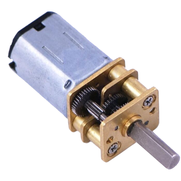
- Rated Voltage: This is the maximum voltage that the motor can be powered with. You can use less voltage than this rated voltage, but it will produce lower speeds and torque. There is also a minimum voltage that the motor needs to work. For example, this 24 V Polulu motor can be operated at 12 Volts and 6 Volts with less performance, but it struggles to operate below 1.5 Volts. This is because there is friction within the motor that acts as a load, and too low of a voltage means the motor will not produce enough torque to overcome it.
- No-load Speed: This is the fastest speed that the DC motor can operate at under no-load conditions and is typically listed in RPM.
- Current Draw: Like servos, there will typically be a current rating at no-load and stall conditions. The no-load current is the minimum current the motor can draw when it is spinning freely without any load attached to the shaft. Stall current is the maximum amount of current the motor can draw under stall conditions. You should always prepare for this stall current and ensure your power supply and circuitry can handle this maximum value.
- Torque: DC motors will have a stall torque (also called peak torque) and this is the maximum torque the motor can be loaded with (remember it will stall at this torque). Running a motor constantly near its peak torque can wear it out, so sometimes there is a second torque rating listed - the continuous torque. This is an amount of torque that the motor can continuously output without overheating or causing damage. Many times we are not that lucky and it will not be listed, but a good rule of thumb is to try and keep the motor at around 25% of its peak torque.
- Gear ratio: DC motors can come with handy inbuilt gearboxes. These often gear down the motor, reducing speed but increasing its torque output, and the gear ratio is a number representing this.
Brushless DC Motors
So far we have been referring just to brushed DC motors, but brushless motors are also a form of DC motors and have their own unique properties and advantages worth discussing. Brushless DC motors, are similar to their brushed counterpart but differ in internal construction and operation. We won't dive too deep into brushless motors, but it is worth knowing a little about them.
Advantages of a Brushless Motor:
- Efficiency: Brushes inside of a motor generate friction and heat, and the absence of these allows for greater efficiency.
- Longer Lifespan: Brushes will often be the first part to wear out in a brushed motor. So this motor technology without them leads to a longer lifetime.
- Greater Power to Weight Ratio: Brushless motors will typically be more powerful than their brushed cousins and weigh far less.
This makes brushless motors great for applications that require high power and greater efficiency like e-bikes and drones. However, brushless motors are more complex in their operation and need a more complex motor driver to account for this. This leads to them being a bit more expensive and difficult to utilise.

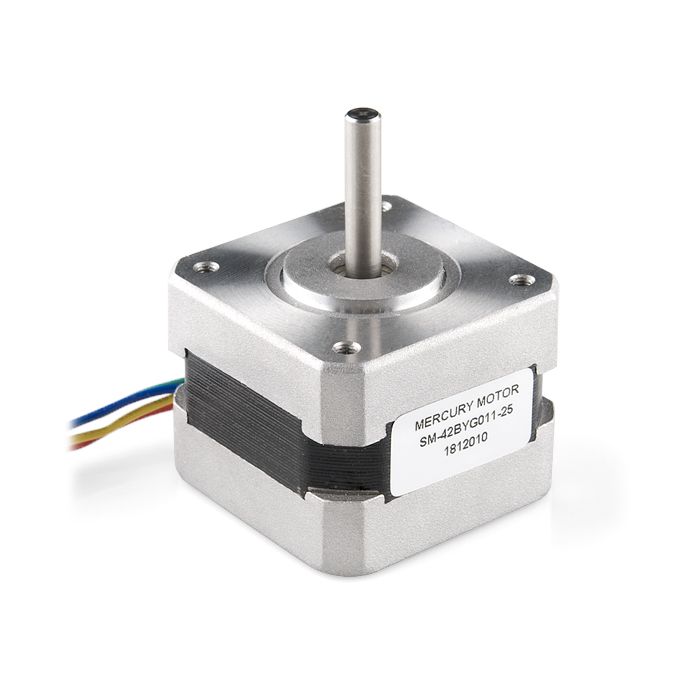
Stepper Motors
Like DC motors, stepper motors generate internal magnetic fields to produce rotational motion, but they do so in steps. While DC motors are great for situations where speed and power are key, stepper motors are perfect when precise positioning is needed, thanks to their ability to move in these discrete steps. They are similar to DC motors in that they allow for full and continuous revolutions, but unlike a DC motor and more like a servo, they can be set to and held at a precise angle. They are kind of the middle ground between a servo and a DC motor.
Characteristics of Stepper Motors:
- Stepping: The reason they are called stepper motors is because they move in discrete "steps". This allows for precise control as the number of steps is known. A common number of steps is 200 per revolution, so if we wished to rotate exactly 90 degrees, we would rotate by 50 steps. This system allows us to set precise angles and rotational speeds. (Steppers can also "microstep" which allows them to be set to a position between these steps, e.g. rotating by 50.2 steps.)
- Holding Torque: A unique ability of stepper motors is that they can be set to a specific angle and hold a load at that angle. For a DC motor to exert a torque while not rotating, it would need to be held under stall conditions, and this would burn the motor out very quickly. However, a stepper motor is able to be set to a precise angle and held there like a servo, and this torque that it can apply at this angle without being is called the holding torque.
- No Feedback System: If we set a stepper to a specific angle, and then apply a greater load than it can handle, it will "jump" backwards a few steps and create a positional error. The advantage of a SERVO is that it has an internal feedback system that would return the servo to the angle it was set to, a stepper does not as it doesn't "know" what angle it is currently at.
- Slow Speeds: Stepper motors are not known for their speed. Although their stepping motion brings precision, it doesn't allow for the higher RPMs that DC motors may be capable of. A good rule of thumb is that most stepper motors have a maximum RPM of about 800-1000, but running nearer to these speeds may give you some problems. Some like this...
- Requires Hardware: Stepper motors require a stepper motor driver or controller to operate, which allows you to easily control the motor from a microcontroller through PWM signals.
- More Complex Setup: Stepper motors come in a wide variety of setups, sometimes they have 4 wires, sometimes they have 7. The amount of wires relate to the type of stepper motor and each one will need to be connected to a driver board in a different manner.
A familiar example of stepper motors is in 3D printers where they are used with pulleys, belts and screws to move the print head around. DC motors are ill-suited as they cannot be set to precise angles, nor do they have the strong holding force that steppers possess. Servos would be ill-suited as they have a limited range of motion, and the belts and pulleys of our printer require multiple rotations to move the print head around.
However, a valuable advantage that SERVOS would bring to this situation is that they always know where they are. If a 3D printer with stepper motors is turned on, it does not know what angle the steppers are currently at. 3D printers offset this by rotating the stepper motors as far as they go in an axis, where it will then press a switch and let the printer know it has reached the end.
At this point, the printer knows where the stepper motors and printer head are at, and can now move it anywhere with precision. The reason we bring this up is because it is common to use some form of a sensor to know the angle or position of a stepper motor.


Vending machines also use stepper motors to rotate the internal coils that dispense food and drinks. A stepper motor is perfect as it can provide multiple revolutions, and the ability to set precise enough angles and speeds to only allow one item at a time to fall.
It also doesn't need to know where it is through any positional feedback. If the item is sitting in the coil the stepper only needs to rotate a known amount of times to push that item out.
Stepper Motor Specifications
There is a wide range of steppers to choose from and several key factors to consider when choosing one for your application. Let's quickly discuss some important ones:
- Step Angle: This is the size of each step in degrees and sometimes it is listed in steps per rotation (dividing by 360 will give you the step angle). One of the most common step angles is 1.8 degrees (or 200 steps per revolution).
- Rated Voltage: This is the maximum Voltage that the stepper motor can be powered with. You can supply less Voltage but will receive less maximum torque.
- Phase: Inside a stepper motor are a series of coils that activate in a calculated way to step the motor. These coils are placed on a number of "teams" that work together and activate at the same time. 2 Phase steppers are very common and have 2 teams inside of them working in sync, and activating at the same time.
- Current Rating: This is the maximum current that each phase of the motor can draw. There are different control strategies when driving a stepper, for example, wave mode activates only 1 phase at a time, but other modes can activate all the phases at once. So the total current draw will depend on how you control it, but anticipate for current per phase multiplied by the number of phases.
- Holding Torque: Stepper motors can typically apply the greatest amount of torque when not moving (but still powered), and the holding torque is the maximum torque that can be applied in this state without overcoming the motor and causing it to "jump" a few steps. Stepper motors can also hold a small amount of torque when NOT powered, and this is called detente torque (just a handy ability that you may be able to use).
Linear Actuators
Linear actuators are, as the name suggests, actuators that produce linear motion. They are typically composed of a DC motor and a gearbox that produces geared-down linear motion which extends and retracts a piston rod - usually with limit switches at either ends which prevent the push rod from being over-extended.
Characteristics of a Linear Actuator:
- Static Loading: A common ability of the linear actuator is the ability to hold a load, even when no power is supplied. Many linear actuators utilise something called a worm gear which makes it easy for the motor to extend and retract the piston rod, but not the other way around. This means that even if you pushed as hard as you could on the piston rod, you would not be able to rotate the motor, and the piston rod would not move. This ability allows linear actuators to hold a force when not in operation.
- Strength: Linear actuators can pack a punch. This linear actuator is small, light and runs on 6 Volts, yet is able to provide 12 kg-f of force, and larger actuators like this Polulu branded one are able to provide up to 450 kg-f of force, 2 of these could lift a small car!
- Precise Positioning (maybe): Most linear actuators have the option to come with a positional feedback mechanism that allows for the accurate measurement of the piston rod's exact position.
- Simple Operation: A linear actuator without any positional feedback will most likely come with only 2 wires. Apply a voltage and it will extend, reverse the voltage and it will retract. Linear actuators with positional feedback will have more wires that will provide positional data, but extend and retract exactly the same. This means a linear actuator can be driven with a MOSFET or a motor driver which allows for the actuator to be controlled with a PWM signal from a microcontroller.
A great example of a linear actuator application is in an adjustable height desk and this is because of a few reasons:
- They provide smooth linear motion to raise and lower the desk.
- They aren't very fast but in this application it isn't critical.
- The typically high dynamic load is enough to lift the weight of the table and everything on it.
- The static loading ability means that we do not have to power the actuator to keep the desk at the height once it is set.
- The table is not continuously being raised and lowered so we do not have duty cycle issues.

Specifications
Linear actuators come in many shapes and sizes that are suitable for a wide variety of applications. To choose the right actuator for the right job, here are some common specifications to understand:
- Rated Voltage: This is the maximum voltage that can be supplied to the actuator. Less voltage can be supplied, but this will result in slower speeds and less output force.
- Stroke Length: This is the whole length that the piston rod can be extended and represents the total size difference between fully extended and fully retracted.
- Dynamic Load Rating: This is the maximum force that the actuator can safely output when powered. This is usually below its stall load, meaning it will still be able to move even when subject to this rated load. Load is typically listed in kg-f or Newtons.
- Static Load Rating: This is the maximum load that can be applied to the actuator without damaging it or causing the actuator's worm gear to slip.
- Speed: Actuators commonly have 2 speeds listed - the no-load speed and the max-load speed. These are representative of their names and are the speeds when no load is applied on the actuator, and when the actuator is loaded to its maximum dynamic load.
- Gear Ratio: A linear actuator series will usually contain different gear ratios. A higher gear ratio reduces the speed of the actuator but increases its force output.
- Duty Cycle: Even if a linear actuator is operated within its load ratings, it cannot be operated continuously as it will overheat. The duty cycle represents the maximum percentage of time it can be operated. Often there is a timeframe of this percentage, but a very safe rule of thumb for actuators is 4 minutes. This means that if we had a duty cycle of 25%, every 4 minutes the actuator can only be operated for a total of 1 minute continuously. A 4-minute window may be overly cautious so check the datasheet for your specific actuator.
Linear Solenoids
Solenoids are another type of actuator that provide linear motion but come with their own unique quirks. A solenoid is composed of wire wrapped into an electromagnet coil with a rod (often called the plunger) through the centre of this coil. When the coil is powered, the plunger is pushed away, and when it is unpowered, the plunger is pulled back into its starting position by a spring.

Characteristics of a Solenoid:
- On-Off: Most solenoids only have 2 positions, fully extended and fully retracted, and it is nearly impossible to set the solenoid to a position between these 2 extremes. Some solenoids may come with multiple positions (such as 3-position solenoids that have a middle position), but they are fairly rare.
- Simplicity: Solenoids have 2 wires protruding from them, and if a voltage is supplied across these wires, it will energise and extend, and if a voltage isn't applied it will de-energise and retract back. There are only 2 possible positions that it can be regulated to, and this provides a great deal of simplicity as it does not need a driver or controller board like other actuators.
- Short Throw Distance: Solenoids typically move a very short distance, usually a few millimetres or a couple of centimetres at most.
- Fast Response: Especially when under no-load conditions, solenoids will actuate between their energised and de-energised state very quickly.
- Non-Continuous Operation: A solenoid cannot be operated continuously as it will very quickly overheat, so we must allow it time to cool down. While every solenoid is different, a general rule of thumb is to power it for a maximum of 5-15 seconds at a time (if you are lucky this time might be on a datasheet).
- Requires Hardware: Driving a solenoid directly from a microcontroller may not be possible as the power required may be too great. However, a solenoid can be easily driven with a MOSFET acting as a switch and we have a guide on how to do that. It is also recommended to use a flywheel diode in your solenoid circuit.
A great example of an application of a linear solenoid is in a pinball machine. The flipper that you use to whack the ball is most often controlled with a linear solenoid. The flipper only needs to be actuated to 2 positions, retracted and fully extended to hit the ball and this fits the solenoid's range of motion perfectly. Solenoids also have a fast response rate which is important in a fast-paced game like pinball.

Specifications:
- Stroke Length: This is the total distance the plunger can move from fully retracted, to fully extended.
- Starting and Retentive Force: There are 2 force ratings on a solenoid at different stages of its operation and will be listed in kg-f or Newtons. A solenoid exerts the most force when it "locks" into its energised state (fully extended), and this force is known as its retentive force. However, before it "locks" into this state, when it is moving from its retracted to its extended state, it won't be able to exert as much force - this is called the starting force.
- Operational Voltage: This is the maximum voltage that the solenoid can be supplied. Less power can be utilised, but the solenoid will move slower and output less force.
- Current: This is simply the peak current that the actuator will be able to draw.
- Duty Cycle: The duty cycle is the maximum percentage of time that it can be operated over a window of time. For example, if a solenoid had a duty cycle of 50%, over a 1 minute period we can only operate it for a maximum of 30 seconds (also remembering that we can only continuously operate it for 5-15 seconds at a time).
Conclusion
Whether you read just the intro or if you have gotten through the entire guide we hope that this has shed some light on different types of actuators. A lot of the time there is no one correct actuator for an application and a variety of actuators can be used for the job. If you have any questions about actuators or applications or even if its right for your project, feel free to post in the forum at the end of this page.
We are all makers and are happy to help!

