In this tutorial, we are going to connect a Motor to the Raspberry Pi and create a hypnotic self-spinner. We are first going to look at how to wire the Raspberry Pi to the motor controller and the motor. We will then look at using the raspberry pi to control the direction and speed using PWM outputs. Finally, we are going to have a quick look at something engineers call Open Loop Control. Let's get started!
What we need
- Raspberry Pi B+ (Any Pi will work Just make sure you check the GPIO pins)
- SparkFun Motor Driver or SparkFun Motor Driver - Dual TB6612FNG
- Hobby Motor - Gear (Any DC motor will work Just adjust your motor supply accordingly)
- Prototyping Wires
- Solderless Breadboard
- 2 x AA Battery Holder (Depending on your motor you may need to adjust this.)
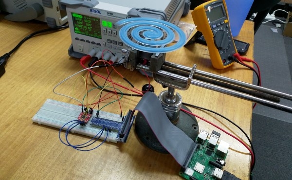
Something cool to spin! I am using this one made by Aidan on our 3D printers! Now let's build the circuit.
The Circuit
I have chosen the SparkFun Motor Driver because it is relatively simple to use and most importantly supports operating voltages from 2.7 to 5.5 volts, the Pi works at 3.3V (5v devices can damage your Pi).
We will work through wiring the Motor driver from the top left pin and work our way around:
|
Motor Driver Pin |
Destination |
Usage |
|
Vm (pin 1) |
Battery +ive |
Motor supply voltage, We are using a 3v supply but this can be up to 15V if your motor will support it. |
|
Vcc (pin 2) |
Pi 3V3 |
3.3V supply from the Raspberry Pi can be from 2.7-5.5V but exceeding 3.3 will damage the Pi. |
|
AO1 (pin 4) |
Motor 1 |
Output For connecting the motor (1.2A max) |
|
AO2 (pin 5) |
Motor 2 |
Output For connecting the motor (1.2A max) |
|
GND (pin 8) |
Pi GND, Battery Negative |
Connect to create a common reference. |
|
PWMA (pin 9) |
Pi GPIO 24 |
Speed control, we will program this pin to generate a PWM signal that will set the motor speed. |
|
AI2 (pin 10) |
Pi GPIO 23 |
Motor Direction Pin |
|
AI1 (pin 11) |
Pi GPIO 18 |
Motor Direction Pin |
|
STBY (pin 12) |
Pi 3V3 |
Standby pin We will connect to 3.3 so it is always on. |
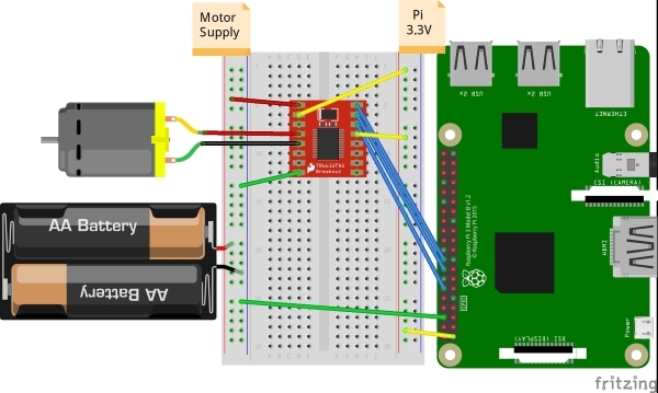
Most importantly we need to make sure we get Vcc and Vm around the right way if we were using a 15V battery mixing them up would cook the motor board and the Pi.
AO1 and AO2 are where we attach the motor, it does not matter which way you connect this, it will just change the direction the motor spins.
PWMA, AI1, and AI2 control the speed and direction of the motor by controlling the H-bridge in the Motor driver. PWMA controls the speed of the motor through Pulse Width Modulation (PWM) and works by switching off the power for a percentage of the time. The STBY pin is like an on-button, we always want the chip on so we will just connect it to the 3.3V supply.
You because of the wide range of operating voltages you can also use this Motor Driver with the Sparkfun red board.
Now that we have our motor and pi all wired up we can get to the coding!
The Script
We are going to use python to write a program that will let us control the speed and direction of the motors.
We are going to use pins 18 and 23 to control the direction we do not want to break so we will only set one of these high at a time.
We will control the speed of the motor by setting the SpeedPWM.value to a number from 0-1, to make this more human-usable we will ask the user for a value from 0- 1000 and divide their answer by 1000.
import gpiozero
import time

#Setup pins
Backward = gpiozero.OutputDevice(18) # On/Off output
Forward = gpiozero.OutputDevice(23) #On/Off output

SpeedPWM = gpiozero.PWMOutputDevice(24) # set up PWM pin

while True:
    directionFlag = input("set motor direction: ")
    if directionFlag == "back": # if user types "back" change direction of motor
        Backward.on() # Sets Backward Direction pin on
        Forward.off() # Sets Backward Direction pin on
    else:
        Backward.off() # Sets Backward Direction off
        Forward.on()   # Sets Backward Direction pin on
    speedFlag = float(input("set speed (between 0-1000): ")) # Gets a number from the from the user
    SpeedPWM.value = speedFlag/1000 # Sets the duty cycle of the PWM between 0-1
Motor Control
Now we have a way to control the speed of the motor by increasing the amount of power to the motors.
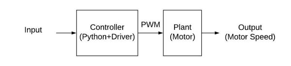
This is called an open loop control scheme, we can make the motor go faster or slower but we don’t have a way to tell it to spin at a specific speed. To do this we need to implement what is called a feedback or closed loop control system, we will talk about them a bit down the track
Motor
I chose the single 3V dc motor I did because it is simple to use and spinning a 3d printed spiral is not a big task and only needs one motor. If you would like to know how to add a second motor or to drive a bigger motor let us know in the comments and we will help you out!
