So, you want to control things with your Particle Photon and/or Electron do you? Well, a relay is a perfect way to do that. Whilst there are many ways to control an electrical signal from digital logic such as transistors and optoisolators, they usually aren’t ideal for certain applications. For example, a transistor may require additional electronic components in order to work like a standard switch, but most transistors can only handle small amounts of power. An optoisolator can only handle extremely small voltages because it’s driving an LED/LDR combo. Which brings us to relays.
We’ll be taking an in-depth look at how relays and solenoids work, which is quite interesting to understand, however beyond that we’ll be looking at how to use the Particle relay board to control various devices. Particle is an incredible platform to use for relay control because it allows you to hook up every day devices and control them via the internet using Particle's incredibly simple, yet powerful cloud functions and webhooks.
The Gear
To follow this tutorial, you'll require the following gear:
- Particle Relay Shield
- Particle Photon or Electron

What is a Relay?
A relay is an electromechanical device which uses a solenoid to make/break the physical conductors which form the switching mechanism. Relays are switches and come in different varieties with different configurations of poles and throws. Relays have the advantage of forming a mechanical path for the electrons to flow, and as such as non-polarized devices, meaning current can flow in either direction. Relays aren’t analogue devices, they are either on or off.
Below is the typical construction of a relay, with a fixed coil, and an armature that pivots to make/break the switch contacts:

Relays have various characteristics/specifications that are important to note when choosing a relay for your project.
We’ll look first at the important electrical specifications:
- Maximum load voltage: This is the maximum voltage that the switch mechanism can handle. Some relays are tiny; designed for small signal switching and can only handle a small voltage. Others, however, can handle mains 240V and more! Which brings us to an important point:
NEVER deal with mains power (240V AC) unless you are licensed to do so. Just because you know how to wire something, doesn’t mean you should, and the consequences of something going wrong with mains power are lethal!
- Maximum load current: This is the maximum current that the switch mechanism can handle. Similar to the voltage, there are different current ratings for different types/sizes of solenoids. It’s important to note that the voltage and current rating of a relay creates a power rating (Voltage x Current = Power), which means that if you switch half of the max voltage, you can switch double the max current.
**Note that whilst you shouldn’t use a relay that’s rated lower than you power usage, you can use a bigger, beefier relay to switch smaller loads**
- Control voltage: The control voltage may be a fixed voltage or a range of voltages that the relay will accept to successfully energise the coil to activate the relay. Make sure you stick to the specifications as higher voltage can burn out the solenoid coil, and a lower voltage will fail to energise the coil.
- Control current: The control current is the maximum current that the coil will draw when it’s energised. You need to ensure that your control source can handle the current that the relay will draw. If you’re driving a relay with a microcontroller, be sure to check the max current draw of your pins, or consider using a transistor to drive the relay.
Mechanical specifications:
- Latching or momentary: Some relays, like switches, will hold the position when energised from a pulse, and on another pulse, will revert to the original position. Non-latching relays require constant power to remain active and have a spring to revert to their non-active state. Latching relays have the advantage of not drawing power while being held in either state, however, the holding current for a non-latching relay is considerably less than the initial current required to energise the coil.
- Switch type: Some relays are simple SPST switches, others are more complex DPDT switches.
For more info on how switches work and the different types of switches, check out our All About Switches tutorial.
We discussed the use of a solenoid in a relay previously, so if you’d like to know more about how a solenoid works, read the next section, otherwise skip ahead to controlling a relay with your Particle board.
What is a Solenoid?
A solenoid is a special type of electromagnet which uses the properties of the ‘motor effect’ to create linear motion. The motor effect describes the phenomenon when: ‘an electrical conductor (usually referred to as wire) carrying current, while in the presence of a magnetic field, will experience a force’. This force will either attract the wire or repel the wire, depending on the direction of the current.
This happens because current flowing through a wire will create an electromagnetic field around it, with its strength dependent on the number of turns in the wire coil and the current flowing through it. In the application of a solenoid, the magnetic field created by the wire draws the iron core armature through the coil to create linear motion.
Most solenoids are used as mechanical on/off switches for things such as valves, linear actuators and relays. Solenoids by themselves have a whole bunch of electrical and mechanical specifications which goes beyond the scope of this tutorial, however, check out the Controlling a Solenoid with Arduino tutorial for more info specifically on solenoids.

Using the Particle Relay Board
So now that we’ve looked at how relays and solenoids work, let’s dive into getting started with the Particle Relay shield. This shield is awesome. It has headers which allow to use it with a Photon or Electron, it’s got extra headers for accessing all of the pins not being used for the relays, four 220V 10A relays with onboard drivers, plus a small prototyping area to build your circuit on. All in all, it’s a pretty sweet piece of gear.
The relays are SPDT relays which mean they have a common pin, closed pin, and an open pin with terminal blocks for easy connection. The relay control pins are connected by default to pins D3-D6 on the Particle headers, however, you can break the traces on the underside of the board with a small knife and connect the relays up to any output pin of your choosing. Here is the schematic from Particle for the control circuitry for the relays:
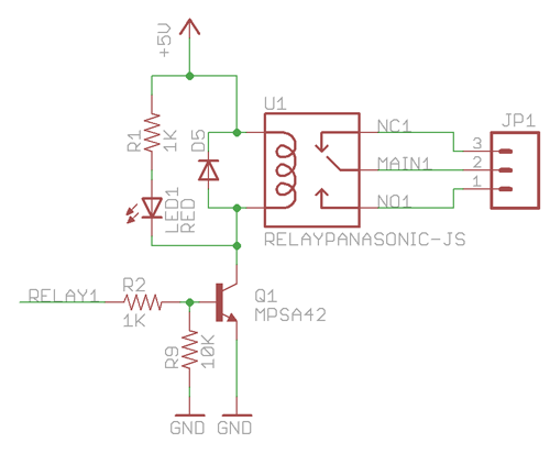
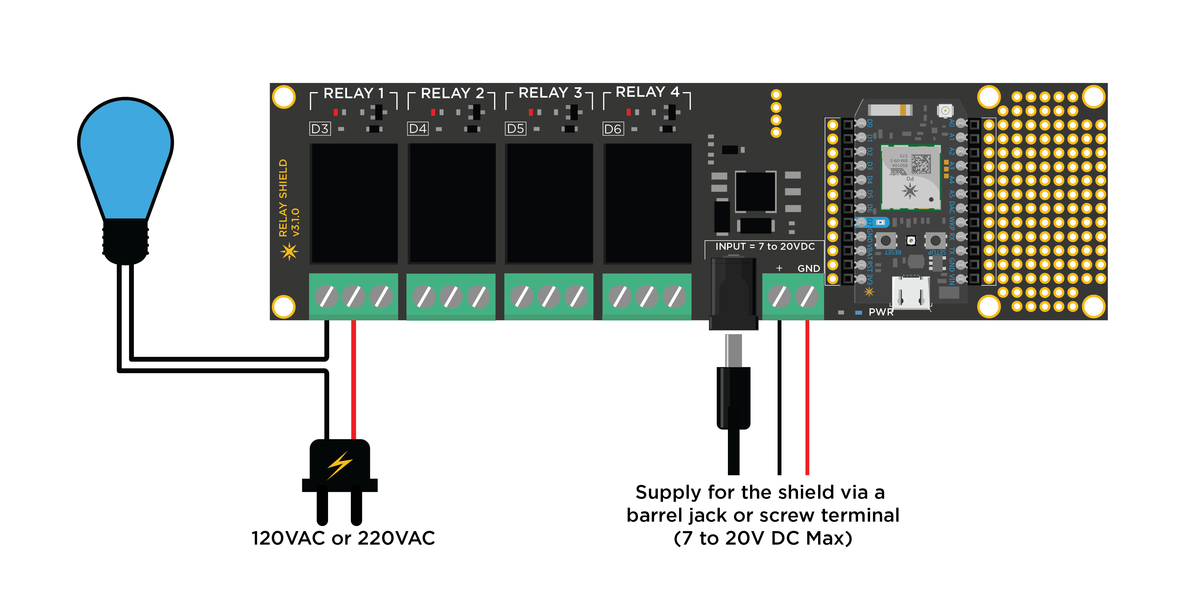
As you can see, they use a transistor buffer to invert the high 3.3V signal to connect the low side of the relay to ground when active, with the high side tied to 5V. Because of the 5V requirement, the Relay shield provides a barrel jack/terminal blocks for connecting 7-20V to power the board, which ties the regulated 5V to the Vin pin on your Particle board.
Because of these connections, though, you are also able to power the Photon/Electron via USB, and the Vin pin connects to the 5V from the USB. This means that provided your USB supply can provide at least 1A, you can power your project and control the relays from the USB supply and you should be ok as far as current demands go. So there are two options for powering the Relay shield.
It’s important to note that if you connect an external power supply to the board, that supply doesn’t power whatever you have connected to the relays, they are just simple, mechanical switches. Whilst the head pins fit the Photon, the Electron has the same pinout for those pins and extends the extra I/O pins beyond that, so you can use the Electron with it and just leave the extra pins overhanging.
Controlling the relays is as easy as turning a digital output on/off. Particle has created a library for using their relay shields, however, it doesn’t provide any extra functionality besides turning one or all of them on/off, so it’s easier just to control them as a digital output and save the overhead compilation that comes along with the library.
You can write whatever code you want to control your relays as they are simply digital outputs, so if you’re not sure how to do that, check out some of our earlier Particle tutorials. However, a fun way to test out the Relay shield is by using the Tinker app to control the relay outputs!
Go ahead and connect something up to the relay, like a motor. Each relay has an LED to indicate whether it’s on or off, so you can test it out, and hear the click of the relay engaging without anything connected up to it. If you’re not familiar with using Tinker, check out our Getting Started with Particle Photon tutorial.
And that’s all there is to using the Particle Relay shield. It’s incredibly easy, and it’s one of the most well designed, cleverly thought out bits of gear we’ve seen. Be sure to comment below with some projects you’ve got in mind, and above all else; USE ELECTRICITY SAFELY!

