 Hello and welcome to our tutorial on using rotary encoders. Today we’re going to be taking a look at what is a rotary encoder, how does it work, why we would use it over other sensory inputs and creating code to use them. Rotary encoders are electromechanical devices which can measure the rotation of a shaft and output data accordingly. There are many different types of rotary encoders which use different technologies and construction materials, however, today we’ll be looking specifically at quadrature rotary encoders which are the most common for general electronics.
How do They Work?
A quadrature rotary encoder is similar to a potentiometer (for more in on these, check out our Potentiometers and Arduino tutorial), however, a rotary encoder doesn’t have limiting points in the rotation; it will rotate infinitely in either direction. Quadrature rotary encoders don’t output an absolute, fixed position, but rather have a number of increments per 360 degrees, and each increment consists of digital pulses known as ‘grey code’. Most encoders have detents which give tactile feedback every time they increment, however, you can also get smooth encoders without detents, usually with a higher number of steps per rotation.
So what is this ‘grey code’ that they output and how can we read it? Well as it turns out, reading gray code is actually quite simple. There is a common pin which connects to ground, then an A and a B pin which carry your signal. A pullup resistor is used to tie the pins high when not connected and when you turn the encoder, the data pins connect to ground to produce low pulses which can be read from a microcontroller pin. Quadrature refers to the fact that the pulses from the A and B data lines are 90 degrees out of phase. This allows you to not only measure when the encoder has being turned, but also what way it has been turned, and by measuring the rate of these pulses, you can determine how quickly it is being turned.
These gray code pulses aren’t a high-speed serial communication, rather a simple, 2-bit signal. The A and B pins act like switches. When you turn the encoder clockwise, it closes the switch for pin A, pulling the line low, and when it reaches the increment, it opens again, where the line is pulled high by the pullup resistors. Pin B acts the same way, except lagging behind pin A by 90 degrees. The opposite is true when You can see this in action in the screenshots taken using a Saleae Logic 8. Note that the uneven spacing between pulses is simply due to the fact that when being turned by hand, the timing of the turns is slightly varied, however as we are looking for the rising and falling edges, the length of the pulse isn’t important (fractions of milliseconds).
Clockwise Rotation

Counter-Clockwise Rotation

To understand what’s going on here a bit better, let’s draw up a truth table of all of the possible values:
|
Clockwise |
Counter-Clockwise |
||
|
A |
B |
A |
B |
|
0 |
1 |
1 |
0 |
|
0 |
0 |
0 |
0 |
|
1 |
0 |
0 |
1 |
|
1 |
1 |
1 |
1 |
When the rotation to the next increment begins, you can see either the A (clockwise) or B (counter-clockwise) channels fall, then the other follows, then the leading pin rises again, followed by the other pin (lagging by 90 degrees).
The good news is that reading the gray code is quite simple. Both pins are held high when there is no rotation, then if we monitor the state of both pins, as soon as one falls low, we compare the other pin, and if it is still high, that means a rotation has begun, and we can determine the direction by which pin was pulled low first.
Now there are a few different ways to do this, but the best method is to use interrupt pins on a microcontroller, that way your program can be doing whatever it wants, and execute a quick function to read the encoder, only when it has been turned. However, because the pins on a rotary encoder act like switches, there are issues such as de-bouncing which need to be taken care of. It’s fairly straight forward to do this, however, Paul Stoffregen from PJRC (the man behind Teensy) has created a fantastic library for using rotary encoders which takes care of all of the de-bouncing and other issues, and allows us easily read the rotation of the encoder. We used a Teensy 3.2 board for the example, however, the library is compatible with any Arduino/Teensy board, and the function can be easily recreated using interrupts and de-bouncing.
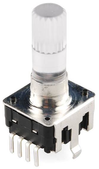
One of the best rotary encoders that we’ve used is the Sparkfun RGB Rotary Encoder as it is solid, has Red, Blue, and Green LEDs mounted inside it which illuminate the clear shaft, and has a built-in switch when you press on the shaft, which makes it perfect for controlling menu displays and user interfaces. The pins have slightly uneven spacing for breadboards so they sell a fantastic breakout board which provides pin labeling and breadboard friendly usage. There's also a bi-colour version of the encoder available which will also work with that same breakout board. You can use any quadrature encoder that you like that outputs gray code, though, but we’ll be using the extra functionality of the LEDs and switch to create various functions in this tutorial.
Wire up your encoder using the pin labeling on the breakout board as a reference:
- A: Data pin A
- B: Data pin B
- C: Ground
- +: Supply voltage (5V or 3.3V depending on your device)
- SW: Switch pin (goes high when pressed, so use a pulldown resistor of around 1K-10K)
- R/G/B: LED control pins (set low to turn on and high to turn off)
Now let's take a look at a really simple implementation of the encoder:
#include <Encoder.h>

long posEnc1;

Encoder enc1(0,1);  //create an object for the encoder

void setup()
{
  Serial.begin(115200); //open a serial port
}

void loop()
{
  long newEnc1; //create variable for holding new encoder value
  newEnc1 = enc1.read()/4;  //read the encoder values, and divide by four to get a single increment/notch
  if (newEnc1 != posEnc1) //if there is a change between the current reading and the last reading
  {
    Serial.println(newEnc1);  //print the current counter
    posEnc1 = newEnc1;  //update the last position to the current position
  }
  delay(1); //delay for stability
}
This is a simple code designed to read the value of the encoder object we created using the encoder library, and when there is a new rotation detected, print the value of an incremental counter to the serial monitor.
So that’s the basics of understanding how quadrature rotary encoders work, and how we can interpret the gray code data that they output. But at Core Electronics, we’re never happy with just understanding the basics, so let’s take a look at using an encoder with a push button, LEDs, and a character display to create a multi-layer menu system, useful for all kinds of projects which require a user interface. We won’t be going into using the character display, Arduino IDE, or LEDs/buttons, only focusing on the rotary encoder usage with the menu. However, we’ve got some great tutorials on these topics which you should check out first if you don’t have a basic understanding of the other technologies we’re using.
You can use whatever type of character display you like, as per our Character Displays with Particle (circuit diagram applies to any platform), or adjust the code to output to the serial monitor. So let’s take a look!
#include <Encoder.h>
#include <LiquidCrystal.h>

int buttonPin = 6;
int enc1R = 20;
int enc1G = 21;
int enc1B = 22;
int ledFlag;
int ledTime;
int turnFlashTime = 100;
const byte debounceTime = 50;
volatile unsigned long lastButtonPress;
volatile boolean buttonPressed = 0;

byte menuLevel;
const byte maxMenuLevel = 1;

int navNum0;
int navNum1;

char* mainMenu[] = {"setting0", "setting1", "setting2"};
char* subMenu0[] = {"submenu0 0", "submenu0 1", "submenu0 2"};
char* subMenu1[] = {"submenu1 0", "submenu1 1", "submenu1 2"};
char* subMenu2[] = {"submenu2 0", "submenu2 1", "submenu2 2"};

int maxMainMenu = 2;
int maxSubMenu0 = 2;
int maxSubMenu1 = 2;
int maxSubMenu2 = 2;

LiquidCrystal lcd(7, 8, 9, 10, 11, 12);

Encoder enc1(0,1);

void setup()
{
  Serial.begin(9600);
  lcd.begin(16,2);
  lcd.print(mainMenu[0]);
  pinMode(buttonPin, INPUT);
  pinMode(enc1R, OUTPUT);
  pinMode(enc1G, OUTPUT);
  pinMode(enc1B, OUTPUT);
  attachInterrupt(digitalPinToInterrupt(buttonPin), button_ISR, CHANGE);

  digitalWrite(enc1R, HIGH);
  digitalWrite(enc1G, HIGH);
  digitalWrite(enc1B, HIGH);
}

void loop()
{
  int newEnc1 = enc1.read()/4;
  if (newEnc1 > 0)  //left
  {
    lcd.clear();
    enc1.write(0);
    menuNav(1);
  }
  if(newEnc1 < 0) //right
  {
    lcd.clear();
    enc1.write(0);
    menuNav(0);
  }
  if(ledFlag == 0 && millis()-ledTime > turnFlashTime)
  {
    ledFlag = 1;
    digitalWrite(enc1G, ledFlag);
    digitalWrite(enc1B, ledFlag);

  }
}

void menuNav(byte dir)
{
  //LEFT
  if(dir == 0)
  {
    ledFlag = 0;
    digitalWrite(enc1G, ledFlag);
    ledTime = millis();
    //TOP MENU LEVEL
    if(menuLevel == 0)
    {
      navNum0--;
      if(navNum0 < 0)
      {
        navNum0 = maxMainMenu;
      }
      lcd.clear();
      lcd.print(mainMenu[navNum0]);
    }
    //SECOND MENU LEVEL
    if(menuLevel == 1)
    {
      lcd.clear();
      switch(navNum0)
      {
        case 0:
          navNum1--;
          if(navNum1 < 0)
          {
            navNum1 = maxSubMenu0;
          }
          lcd.print(subMenu0[navNum1]);
          break;
        case 1:
          navNum1--;
          if(navNum1 < 0)
          {
            navNum1 = maxSubMenu1;
          }
          lcd.print(subMenu1[navNum1]);
          break;
        case 2:
          navNum1--;
          if(navNum1 < 0)
          {
            navNum1 = maxSubMenu2;
          }
          lcd.print(subMenu2[navNum1]);
          break;
      }
    }
  }
  //RIGHT
  if(dir == 1)
  {
    ledFlag = 0;
    digitalWrite(enc1B, ledFlag);
    ledTime = millis();
    //TOP MENU LEVEL
    if(menuLevel == 0)
    {
      navNum0++;
      if(navNum0 > maxMainMenu)
      {
        navNum0 = 0;
      }
      lcd.clear();
      lcd.print(mainMenu[navNum0]);
    }
    //SECOND MENU LEVEL
    if(menuLevel == 1)
    {
      lcd.clear();
      switch(navNum0)
      {
        case 0:
          navNum1++;
          if(navNum1 > maxSubMenu0)
          {
            navNum1 = 0;
          }
          lcd.print(subMenu0[navNum1]);
          break;
        case 1:
          navNum1++;
          if(navNum1 > maxSubMenu1)
          {
            navNum1 = 0;
          }
          lcd.print(subMenu1[navNum1]);
          break;
        case 2:
          navNum1++;
          if(navNum1 > maxSubMenu2)
          {
            navNum1 = 0;
          }
          lcd.print(subMenu2[navNum1]);
          break;
      }
    }
  }
}

void buttonNav()
{
  menuLevel++;
  if(menuLevel > maxMenuLevel)
  {
    menuLevel = 0;
    lcd.clear();
    lcd.print(mainMenu[navNum0]);
  }
  if(menuLevel == 1)
  {
    navNum1 = 0;
    lcd.clear();
    if(navNum0 == 0){
      lcd.print(subMenu0[navNum1]);
    }
    if(navNum0 == 1)
    {
      lcd.print(subMenu1[navNum1]);
    }
    if(navNum0 == 2)
    {
      lcd.print(subMenu2[navNum1]);
    }
  }
}

void button_ISR()
{
  if ((millis()-lastButtonPress) >= debounceTime)
  {
    lastButtonPress = millis ();
    //pressed
    if (digitalRead(buttonPin) == HIGH)
    {
      digitalWrite(enc1R, LOW);
      buttonPressed = 1;
      buttonNav();
    }
    //released
    else {
      digitalWrite(enc1R, HIGH);
      buttonPressed = 0;

    }
  }
}
And there you have it, a menu structure that you can navigate using a rotary encoder, including visual feedback using the LEDs. We've avoided using hardware timers and interrupts in favour of the millis() function, to make the code as portable to other Arduino boards as possible. Whilst there are definitely other ways to create a menu structure, and libraries that can hide a lot of the code, it definitely helps to understand a system by building it from the ground up.
Hopefully this tutorial gave you an insight into how rotary encoders work, how to use them, and some tips and tricks for creating projects and user interfaces with Arduino compatible boards.

