This project aims to fuse neopixel strips with papier mache and origami into a free-standing electro-sculpture.
The freestanding structure is formed from wire mesh and papier mache. It is then painted and wired up with strips of LEDs connected to an RPi3+Teensy+OctoWS2811 Adapter + Power Supply. The entire LED covered surface is then covered in a diffuser created from modular origami elements glued together. Finally, some VJ software (Glediator) is used to create realtime animated patterned displays.
Parts Used
- 17x Neopixel strips (60/m)
- Raspberry Pi 3
- Teensy 3.6
- OctoWS2811 adapter
- 5v 60A Power brick
- Arduino Mega
- Powerbank
- Miscellaneous hardware (wire mesh, fencing wire, PVA glue, newspaper, paint)
- Hookup wire
- CAT6 Ethernet cable
- Micro USB cable + USB housing
- Female USB A to Female USB A adapter (power capable)
- JST connectors
- Crimp connectors/terminals
Equipment Used
- Wire cutters
- Crimpers
- Soldering Iron
- Laser Cutter
I begin by cutting a 1.5m length of wire mesh and forming it into a wave-like shape and temporarily secure with general purpose fencing wire.

The mesh providing sufficient flexibility for shaping and strength for support while being lightweight and easy to work with.
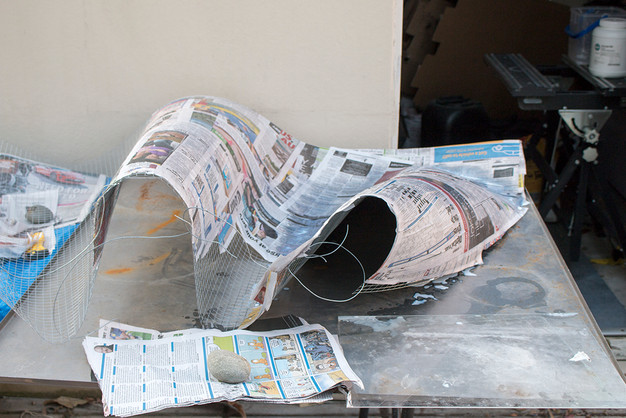

Newspaper and thinned PVA glue is used to build up the thickness of the form providing rigidity and a smoothed surface (given I'm being very careful in the application). PVA is thinned with acetone and was chosen as the binder which would dry very quickly. Traditional glue paste made from flour and water would take a long time to dry and has a tendency to mould. This method also exploits PVA's plasticity and flexibility.
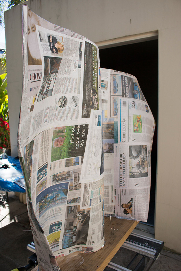
Two coats of white matte paint are sprayed over the surfaces to sufficiently mask the newsprint.

To expedite the process of making origami en-mass, I translated the design into a number of templates using Illustrator and laser cutting these from clear acrylic sheet. Two sizes were created, one based on a 13mm grid design and the other on 26mm. Three template layers are used for each, one for cutting the base squares from paper sheets, the second includes alignment marks as well as the 'valley' fold creases while the third contains the 'mountain' fold crease patterns.These tools have greatly increased productivity.

The acrylic templates are used to impart score marks required for the fold creases. This saves a LOT of time as it eliminates the need to rule grids and lines.


At this point, I have folded more than 600 individual units. Given my productivity rate is about 30 per hour that's over 20 hours of work origamiing alone!

After I started assembling the units, I noticed the two shades of white in the paper... this is a result of using two different reams of copy paper and I decided to stick with this so alternate the paper source with each batch. I quite like the subtle effect which will be completely unnoticeable with the lights behind it.
Checking the size of the assembly against the papier mache structure and testing how the origami layer will conform to the undulating substrate - this is shaping up very nicely... though still a bit of folding to go :(

Finally! With a grand total of 851 origami modules...

... preparing the LED strips. These had to be cut to length then each end soldered with three wires; power, earth and data.
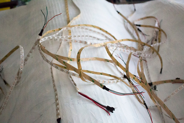
A total of 17 strips are used. The height of the piece reduces the strips to 53 LEDs each for a total of 901.

These strips are the self-adhesive variety but I found that it's not quite strong enough to adhere to the painted surface so have had to add glue to secure in place. Holes were punched through the papier mache at each end of the strip to allow the wiring and electronics to be hidden on the back.
Testing each strip with an Arduino Mega and a power brick to ensure every light performs correctly...

6mm x 10^2mm Laser cut clear acrylic squares are to be glued at regular intervals which should provide sufficient margin between the LED and the origami to diffuse the beams and saturate as much of the activated surface as possible.
Time for the sunnies...

While it was sufficient to use the Arduino Mega controller when testing the LEDs, it simply is not powerful or fast enough to run this number of LEDs.
The solution was constructed using a Raspberry Pi 3, a Teensy 3.6 coupled with the OctoWS2811 adapter which is used to connect vast numbers of LEDs via CAT6 Ethernet cable.
NOTE: This is an advanced project and was in no way straight forward requiring A LOT of research, frustration and hair-pulling.
===================================================================================================
SIDE NOTE ON SOLUTION
This requires the Arduino IDE to be installed on the Pi - there are plenty of tutorials about how to do this on the web.
Once installed, in order for the Teensy to be recognised by the Arduino IDE, the Teensyduino add-on for Arduino IDE must be installed. This can be found at: https://www.pjrc.com/teensy/teensyduino.html and there is an associated tutorial here: https://www.pjrc.com/teensy/tutorial.html
- NOTE: the OctoWS2811 LED Library (required to seemlessy integrate the adapter) is installed with teensyduino
The OctoWS2811 adapter requires some special attention when soldering on the headers given it was not designed with the Teensy 3.6 (or 3.5) in mind as the RJ45 header makes this a bit tricky with the length of these boards. If using the Teensy 3.2 this won't be a problem as the Octo headers fit perfectly with this board. The longer boards require the use of special double insulator pins and sockets to give the extra height needed to clear the RJ45s. These are available from PJRC directly (or you might be lucky to find these elsewhere but are hard to find)... HINT HINT - Core Electronics might consider stocking these!
I couldn't find them anywhere that did not require exhorbitant shipping costs, so I managed to hack together a workaround with extra tall headers:

There is a more information about this (and a tutorial on how to hack the CAT6 cable to wire up the LEDs) at: https://www.pjrc.com/store/octo28_adaptor.html
Since I will be using Glediator to stream pixel animations to the LEDs, a bit of digging around on the PJRC forum found a neat bit of code which provides this functionality: https://forum.pjrc.com/threads/33012-Gladiator-with-OctoWS2811-working-example. This must be uploaded to the Teensy from the Arduino IDE.
More info about Glediator can be found here: http://www.solderlab.de/index.php/software/glediator but it should be noted that this software is quirky and not intuitive to use.
Glediator does not recognise the COM port with the Teensy attached so more digging found that you need to create a symbolic link (on command line) like:
sudo ln -s /dev/ttyACM0 /dev/ttyUSB0
Then with the Glediator software running, under Output Options, the COM-Port should be available - afterwhich you click the Serial Open button and the magic begins.
===================================================================================================
A 5v 60A power distribution brick was used to deliver the power requirements which was also wired to power the Raspberry Pi via a hacked USB. The Teensy/Octo boards are tethered directly to the RPi via micro USB which supplies data and power transmission.

To create a housing for the electronics a design was lasercut from white acrylic sheet - with provisions for ventilation, switches and cables.
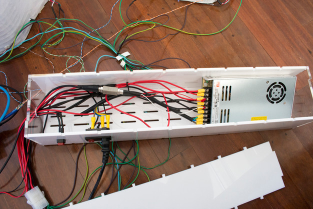
A power switch as well as a 'system shutdown' button were wired in and all cables were crimped and connected using appropriate modular male/female connector hubs.
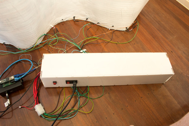
Testing the fully assembled power/computer solution...
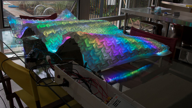
Using Solderlabs' Glediator software to generate animated pixel displays...
While this is a great piece of software, it has its drawbacks. In particular there is no provision to parse parameters at application startup. So while the rest of the system is auto-loading, I still have to remote in (headlessly) to physically select the parameters from within the software... while annoying isn't a show stopper.


