
Magnetic Encoder Pair Kit with Side-Entry Connector for Micro Metal Gearmotors, 12 CPR, 2.7-18V
In stock, ships same business day if ordered before 2PM
Delivered by Tue, 23rd of Apr
Quantity Discounts:
- 10-25 $11.86 (exc GST)
- 25+ $11.62 (exc GST)
Recommended Essentials:

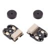
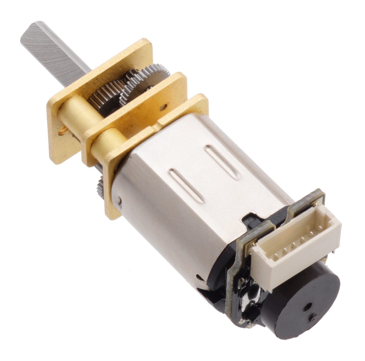
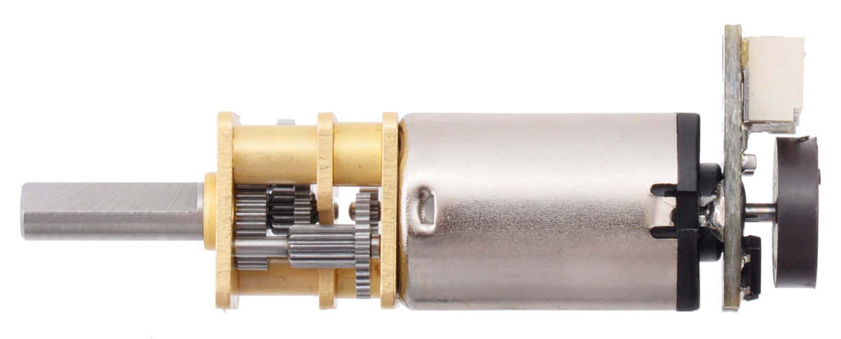
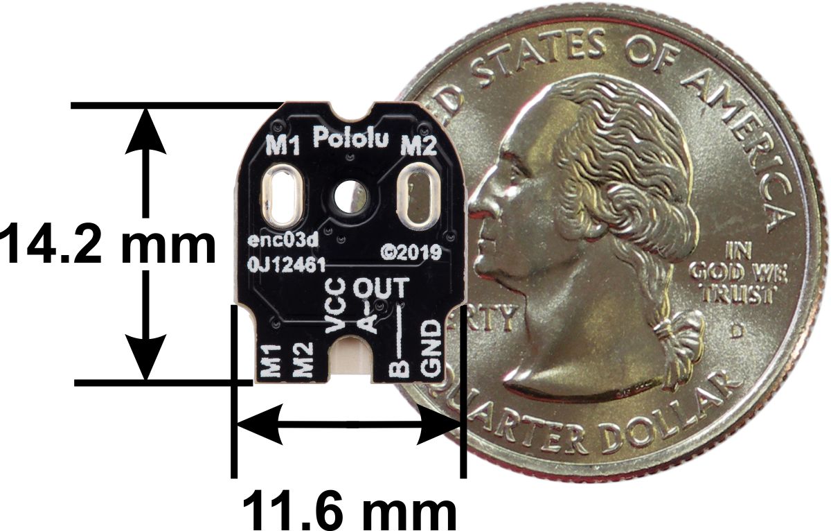
This kit includes two dual-channel Hall effect sensor boards and two 6-pole magnetic discs that can be used to add quadrature encoding to two micro metal gearmotors with extended back shafts (motors and cables are not included with this kit). The encoder board senses the rotation of the magnetic disc and provides a resolution of 12 counts per revolution of the motor shaft when counting both edges of both channels. To compute the counts per revolution of the gearbox output shaft, multiply the gear ratio by 12. This compact encoder solution fits within the 12 mm × 10 mm cross section of the motors on three of the four sides, and it extends 4.2 mm past the edge of the fourth side.
|
|
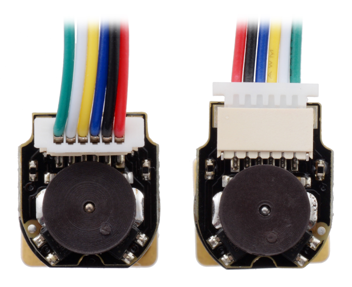
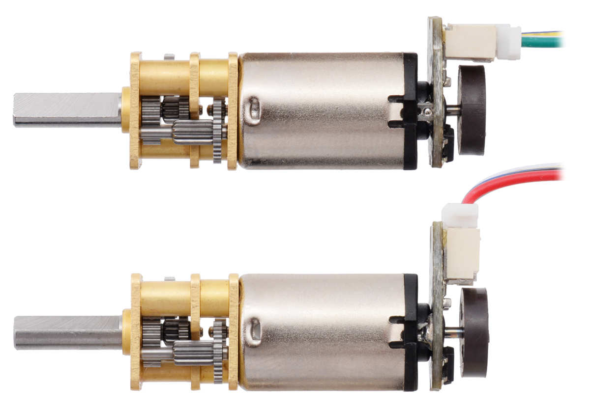
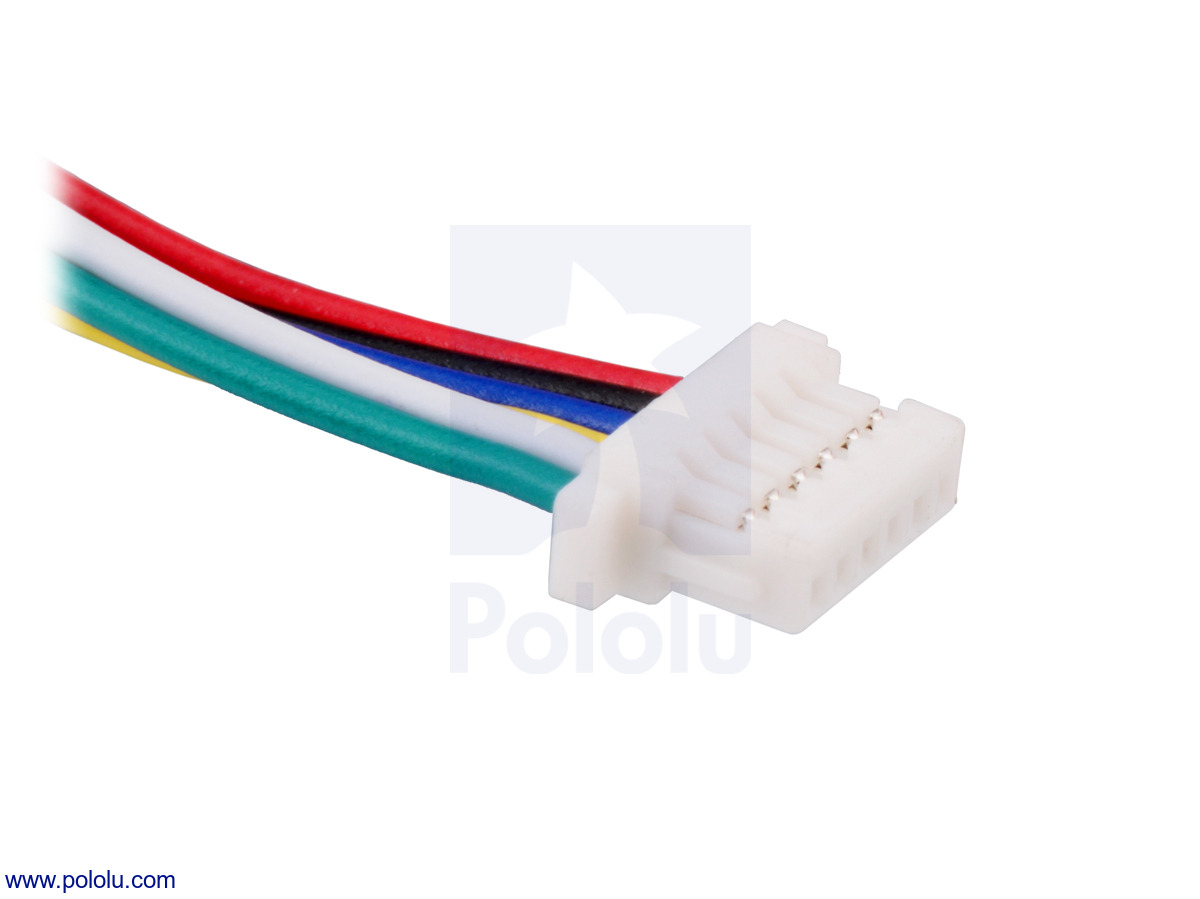
The encoders include a side-entry, 6-pin male JST SH-type connector. Pololu also carry a version of this encoder with a top-entry connector; the following pictures show comparisons of the top-entry and side-entry versions:
|
|
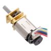
Note: This sensor system is intended for users comfortable with the physical encoder installation. It only works with micro metal gearmotors that have extended back shafts.
Cable options
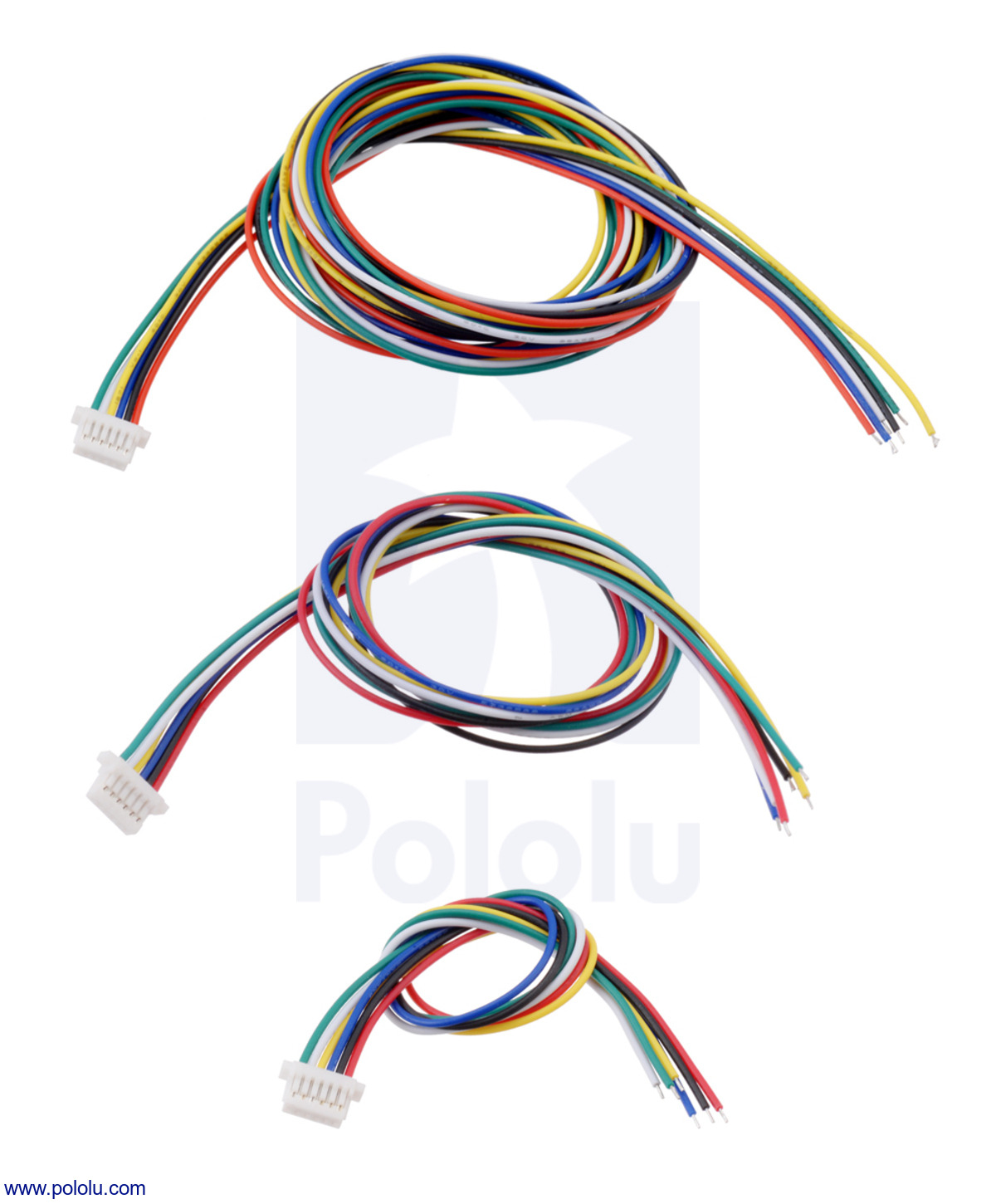
Pololu have two types of cables with matching JST SH-style connectors that can be used with these encoders.
Single-ended cables, with a connector on one end and unterminated wires on the other end, are available in three lengths:
 |
Twisted female-female cables with connectors on both ends are available in five lengths:
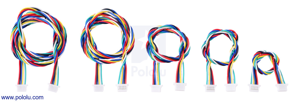 |
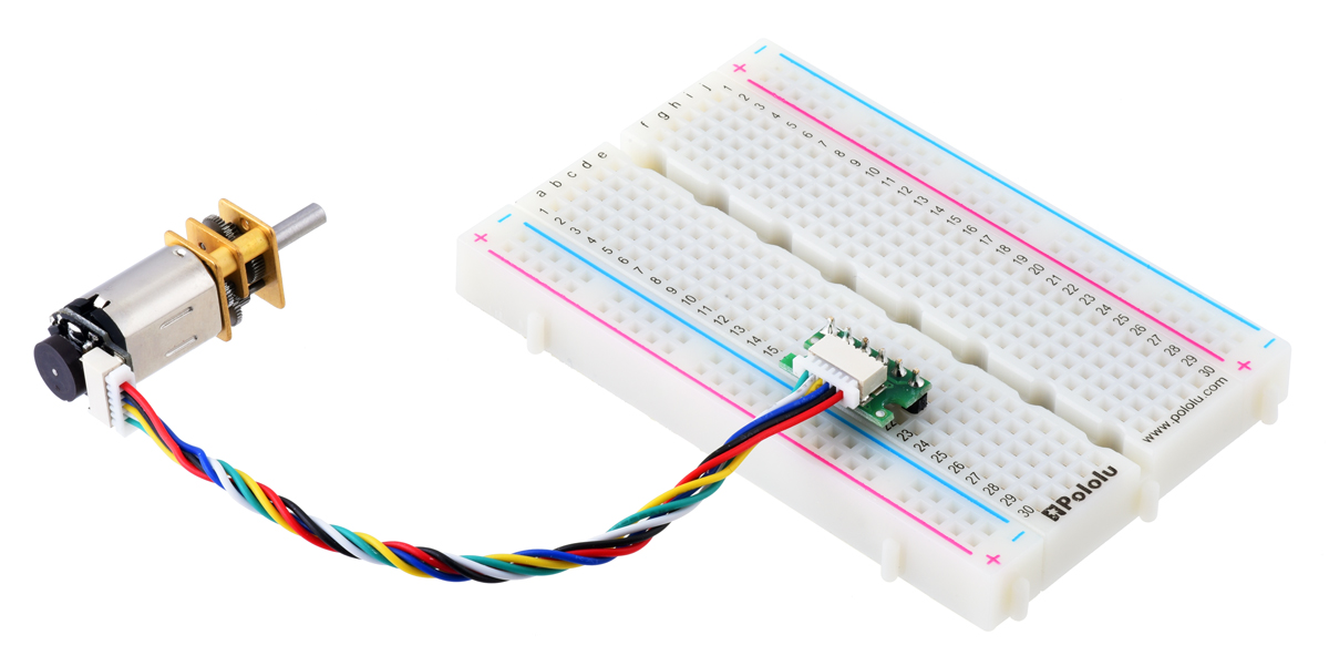
These double-ended cables can be used with Pololu's JST SH-style connector breakout boards (available in top-entry and side-entry versions) to easily access the motor and encoder pins on a standard solderless breadboard.
|
|
Pinout and installation
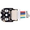
The encoder board is designed to be soldered directly to the back of the motor, with the back shaft of the motor protruding through the hole in the middle of the circuit board. One way to achieve good alignment between the board and the motor is to tack down the board to one motor pin and to solder the other pin only when the board is flat and well aligned. Be careful to avoid prolonged heating of the motor pins, which could deform the plastic end cap of the motor or the motor brushes. Once the board is soldered down to the two terminals, the motor leads are connected to the M1 and M2 connector pins as labeled below, and they can be accessed via the red and black wires when used with Pololu's corresponding JST cables. The remaining four connector pins are used to power the sensors and access the two quadrature outputs:
|
|
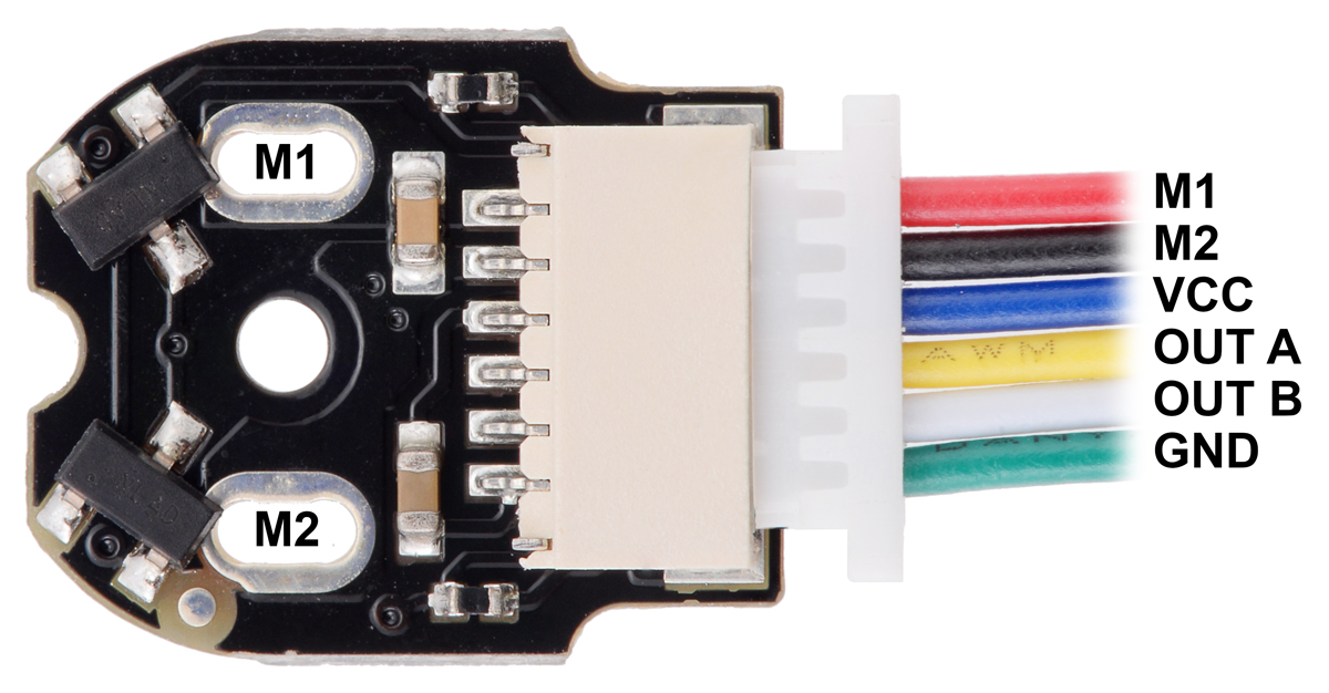
The sensors are powered through the VCC (blue wire) and GND (green wire) pins. VCC can be 2.7 V to 18 V, and the quadrature outputs A and B (yellow and white wires) are digital signals that are either driven low (0 V) by the sensors or pulled to VCC through 10 kO pull-up resistors, depending on the applied magnetic field. The sensors’ comparators have built-in hysteresis, which prevents spurious signals in cases where the motor stops near a transition point.
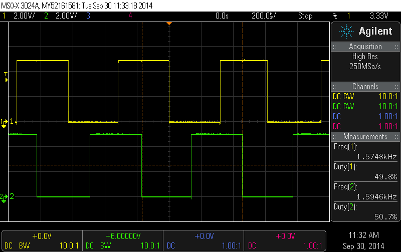 |
Encoder A and B outputs of a magnetic encoder on a high-power (HP) micro metal gearmotor running at 6 V. |
|---|
Schematic diagram
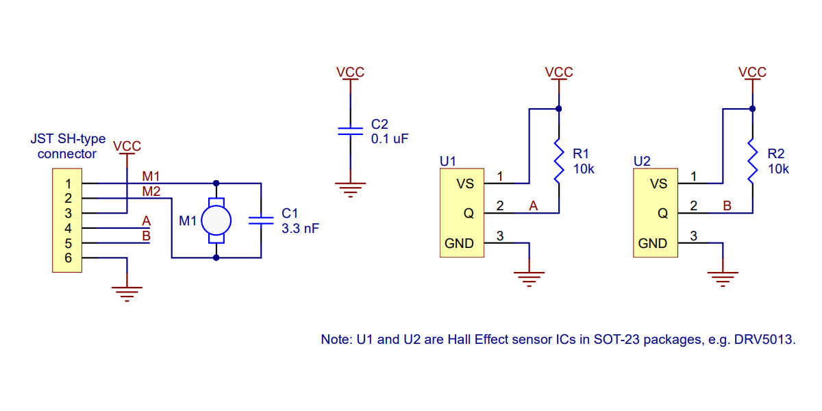 |
This schematic is also available as a downloadable pdf (80k pdf).
Comparison to previous version
This encoder version is a modification of the previous version that adds a connector to enable the use of removable cables. The basic schematic is unchanged, and the electrical performance is identical. The following picture shows the two new encoders with JST SH-type connectors next to the previous (green) one:
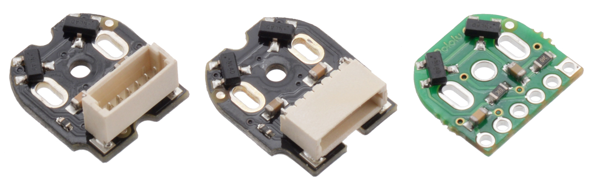 |
Side-by-side comparison of Magnetic Encoder with Top-Entry Connector (left), Side-Entry Connector (center), and 2mm-pitch through-holes (right). |
|---|
People often buy this product together with:
 | Pololu Micro Metal Gearmotor Bracket Pair - Black |
 | Magnetic Encoder Pair Kit with Top-Entry Connector for Micro Metal Gearmotors, 12 CPR, 2.7-18V |
 | 6-Pin Single-Ended Female JST SH-Style Cable 12cm |
Dimensions
| Size: | 14.2 mm × 11.6 mm1 |
|---|---|
| Weight: | 1.5 g2 |
General specifications
| Minimum operating voltage: | 2.7 V |
|---|---|
| Maximum operating voltage: | 18 V |
| Connector: | side-entry, 6-pin male, JST SH-type |
Identifying markings
| PCB dev codes: | enc03d |
|---|---|
| Other PCB markings: | 0J12461 |
Notes:
- 1
- The assembled encoder will extend approximately 5 mm beyond the plastic motor end cap.
- 2
- Weight of full set. Each encoder board weighs ~0.4 g and each magnet disc weighs ~0.3 g.
File downloads
-
This file contains dimension diagrams for the Magnetic Encoder Pair Kit with Top-Entry Connector and the Magnetic Encoder Pair Kit with Side-Entry Connector.
-
This file contains 3D models (in the step file format) of the components for the Magnetic Encoder Pair Kit with Top-Entry Connector and the Magnetic Encoder Pair Kit with Side-Entry Connector.
-
These DXF drawings show the locations of all of the holes on the Magnetic Encoder Pair Kit with Top-Entry Connector (enc03c) and the Magnetic Encoder Pair Kit with Side-Entry Connector (enc03d).
Recommended links
This product is listed in:
Sensors>EncodersComponents & Parts>Motors>Metal Gearmotors>Mounting & Accessories
Exact shipping can be calculated on the view cart page (no login required).
Products that weigh more than 0.5 KG may cost more than what's shown (for example, test equipment, machines, >500mL liquids, etc).
We deliver Australia-wide with these options (depends on the final destination - you can get a quote on the view cart page):
- $3+ for Stamped Mail (typically 10+ business days, not tracked, only available on selected small items)
- $6+ for Standard Post (typically 6+ business days, tracked)
- $10+ for Express Post (typically 2+ business days, tracked)
- Pickup - Free! Only available to customers who live in the Newcastle region (must order online and only pickup after we email to notify you the order is ready). Orders placed after 2PM may not be ready until the following business day.
Non-metro addresses in WA, NT, SA & TAS can take 2+ days in addition to the above information.
Some batteries (such as LiPo) can't be shipped by Air. During checkout, Express Post and International Methods will not be an option if you have that type of battery in your shopping cart.
International Orders - the following rates are for New Zealand and will vary for other countries:
- $11+ for Pack and Track (3+ days, tracked)
- $16+ for Express International (2-5 days, tracked)
If you order lots of gear, the postage amount will increase based on the weight of your order.
Our physical address (here's a PDF which includes other key business details):
Unit 18, 132 Garden Grove Parade
Adamstown
NSW, 2289
Australia
Take a look at our customer service page if you have other questions such as "do we do purchase orders" (yes!) or "are prices GST inclusive" (yes they are!). We're here to help - get in touch with us to talk shop.
Have a product question? We're here to help!
 Magnetic Encoder Pair Kit for Micro Metal Gearmotors, 12 CPR, 2.7-18V (HPCB compatible)SKU: POLOLU-3081 Brand: PololuAdd quadrature encoders to your micro metal gearmotors (extended back shaft vers ...
- Magnetic Encoder Pair Kit with Top-Entry Connector for Micro Metal Gearmotors, 12 CPR, 2.7-18VSKU: POLOLU-4760 Brand: PololuAdd quadrature encoders to your micro metal gearmotors (extended back shaft vers ...
- Raspberry Pi Codec ZeroSKU: CE07560 Brand: Raspberry Pi
The Raspberry Pi Codec Zero is a Raspberry Pi Zero-sized audio I/O HAT. It de ...
- Raspberry Pi DAC+SKU: CE07561 Brand: Raspberry Pi
The Raspberry Pi DAC+ is an audio output HAT for all generations of Raspberry ...


- 6-Pin Female-Female JST SH-Style Cable 10cmSKU: POLOLU-4765 Brand: PololuThis 10 cm (4") cable has six 28 AWG wires and 6-pin female JST SH-type connec ...
- Pololu Micro Metal Gearmotor Bracket Extended PairSKU: POLOLU-1089 Brand: PololuThis compact bracket enables convenient mounting of popular, Sanyo-style micro m ...
- 380:1 Micro Metal Gearmotor MP 6V with Extended Motor ShaftSKU: POLOLU-4793 Brand: PololuThis gearmotor is a miniature medium-power, 6 V brushed DC motor with a 379.17: ...
- 1000:1 Micro Metal Gearmotor HPCB 6V with Extended Motor ShaftSKU: POLOLU-3080 Brand: PololuThis gearmotor is a miniature high-power, 6 V brushed DC motor with long-life c ...


Videos
View AllGuides

Servos, Steppers or Solenoids? | Choosing an Actuator to Move Your Project

How To Control A Motor with the Raspberry Pi

The Maker Revolution

Motor Drivers vs. Motor Controllers
Projects

WhyzaGC - Feather ESP32 addon to the MightyOhm Gieger Counter

DIY Pi Buggy

Makers love reviews as much as you do, please follow this link to review the products you have purchased.
Product Comments