
AltIMU-10 v3 Gyro, Accelerometer, Compass, and Altimeter (L3GD20H, LSM303D, and LPS331AP Carrier)
Retired Product
Replaced by: POLOLU-2739This product is no longer available. This page is only for reference.
Clearance: This board is being replaced by the newer AltIMU-10 v4, which features a newer LPS25H barometer with better accuracy and lower noise than the LPS331AP. The new v4 version is pin-compatible with both this v3 version and the original AltIMU-10, but changes in configuration registers might require some changes to software written for older versions (this should not be an issue if you are using Pololu's Arduino libraries). This product will be discontinued when stock runs out and is not recommended for new designs where continued part availability is important.
 |

Overview
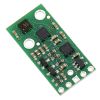
The Pololu AltIMU-10 v3 is a compact (1.0″ × 0.5″) board that combines ST’s LPS331AP digital barometer, L3GD20H 3-axis gyroscope, and LSM303D 3-axis accelerometer and 3-axis magnetometer to form an inertial measurement unit (IMU) and altimeter; Pololu therefore recommend careful reading of the LPS331AP datasheet (453k pdf), L3GD20H datasheet (3MB pdf), and LSM303D datasheet (1MB pdf) before using this product. These sensors are great ICs, but their small packages make them difficult for the typical student or hobbyist to use. They also operate at voltages below 3.6 V, which can make interfacing difficult for microcontrollers operating at 5 V. The AltIMU-10 v3 addresses these issues by incorporating additional electronics, including a voltage regulator and a level-shifting circuit, while keeping the overall size as compact as possible. The board ships fully populated with its SMD components, including the L3GD20H, LSM303D, and LPS331AP, as shown in the product picture.
Compared to the original AltIMU-10, the v3 version offers a number of improvements arising from the use of newer MEMS sensors, including a wider maximum magnetic sensing range and better gyroscopic accuracy and stability. This version also adds a pin for changing the sensor slave addresses, allowing two AltIMUs to be on the same I²C bus. The AltIMU-10 v3 is pin-compatible with the original AltIMU-10, but changes in I²C addresses and configuration registers might require some changes to software written for the older version (this should not be an issue if you are using Pololu's Arduino libraries).
The AltIMU-10 v3 is pin-compatible with the MinIMU-9 v3 and offers the same functionality augmented by a digital barometer that can be used to obtain pressure and altitude measurements. It includes a second mounting hole and is only 0.2″ longer than the MinIMU-9 v3. Any code written for the MinIMU-9 v3 should also work with the AltIMU-10 v3.
 |
| Side-by-side comparison of the MinIMU-9 v3 with the AltIMU-10 v3. |
|---|
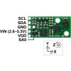
The LPS331AP, L3GD20H, and LSM303D have many configurable options, including selectable resolutions for the barometer and dynamically selectable sensitivities for the gyro, accelerometer, and magnetometer. Each sensor also has a choice of output data rates. The three ICs can be accessed through a shared I²C/TWI interface, allowing the sensors to be addressed individually via a single clock line and a single data line. Additionally, the SA0 pin is accessible, allowing users to change the slave addresses and have two AltIMUs connected on the same I²C bus (For additional information, see the I²C Communication section below).
The nine independent rotation, acceleration, and magnetic readings provide all the data needed to make an attitude and heading reference system (AHRS), and readings from the absolute pressure sensor can be easily converted to altitudes, giving you a total of ten independent measurements (sometimes called 10DOF). With an appropriate algorithm, a microcontroller or computer can use the data to calculate the orientation and height of the AltIMU board. The gyro can be used to very accurately track rotation on a short timescale, while the accelerometer and compass can help compensate for gyro drift over time by providing an absolute frame of reference. The respective axes of the two chips are aligned on the board to facilitate these sensor fusion calculations. (For an example of such a system using an Arduino, see the picture below and the Sample Code section at the bottom of this page.)
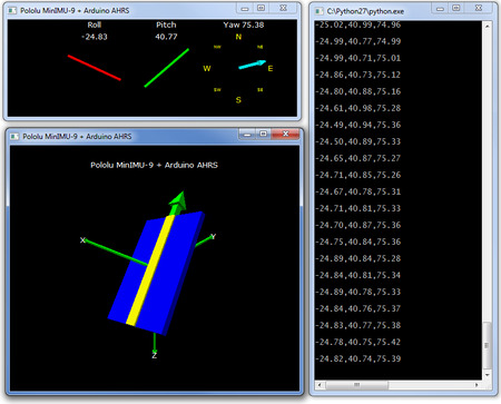 |
| Visualization of AHRS orientation calculated from MinIMU-9 readings. |
|---|
The carrier board includes a low-dropout linear voltage regulator that provides the 3.3 V required by the LPS331AP, L3GD20H, and LSM303D, allowing the module to be powered from a single 2.5 V to 5.5 V supply. The regulator output is available on the VDD pin and can supply almost 150 mA to external devices. The breakout board also includes a circuit that shifts the I²C clock and data lines to the same logic voltage level as the supplied VIN, making it simple to interface the board with 5 V systems. The board’s 0.1″ pin spacing makes it easy to use with standard solderless breadboards and 0.1″ perfboards.
Specifications
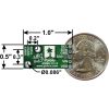
- Dimensions: 1.0″ × 0.5″ × 0.1″ (25 mm × 13 mm × 3 mm)
- Weight without header pins: 0.8 g (0.03 oz)
- Operating voltage: 2.5 V to 5.5 V
- Supply current: 6 mA
- Output format (I²C):
- Gyro: one 16-bit reading per axis
- Accelerometer: one 16-bit reading per axis
- Magnetometer: one 16-bit reading per axis
- Barometer: 24-bit pressure reading (4096 LSb/mbar)
- Sensitivity range:
- Gyro: ±245, ±500, or ±2000°/s
- Accelerometer: ±2, ±4, ±6, ±8, or ±16 g
- Magnetometer: ±2, ±4, ±8, or ±12 gauss
- Barometer: 260 mbar to 1260 mbar (26 kPa to 126 kPa)
Included Components
A 1×6 strip of 0.1″ header pins and a 1×5 strip of 0.1″ right-angle header pins are included, as shown in the picture below. You can solder the header strip of your choice to the board for use with custom cables or solderless breadboards or solder wires directly to the board itself for more compact installations. The board features two mounting holes that work with #2 or M2 screws (not included).
 |
Using the AltIMU-10 v3
Connections
A minimum of four connections are necessary to use the AltIMU-10 v3: VIN, GND, SCL, and SDA. VIN should be connected to a 2.5 V to 5.5 V source, GND to 0 volts, and SCL and SDA should be connected to an I²C bus operating at the same logic level as VIN. (Alternatively, if you are using the board with a 3.3 V system, you can leave VIN disconnected and bypass the built-in regulator by connecting 3.3 V directly to VDD.)
|
|


Pinout
| PIN | Description |
|---|---|
| SCL | Level-shifted I²C clock line: HIGH is VIN, LOW is 0 V |
| SDA | Level-shifted I²C data line: HIGH is VIN, LOW is 0 V |
| GND | The ground (0 V) connection for your power supply. Your I²C control source must also share a common ground with this board. |
| VIN | This is the main 2.5 V to 5.5 V power supply connection. The SCL and SDA level shifters pull the I²C bus high bits up to this level. |
| VDD | 3.3 V regulator output or low-voltage logic power supply, depending on VIN. When VIN is supplied and greater than 3.3 V, VDD is a regulated 3.3 V output that can supply up to approximately 150 mA to external components. Alternatively, when interfacing with a 2.5 V to 3.3 V system, VIN can be left disconnected and power can be supplied directly to VDD. Never supply voltage to VDD when VIN is connected, and never supply more than 3.6 V to VDD. |
| SA0 | 3.3V-logic-level input to determine I²C slave addresses of the three ICs (see below). It is pulled high by default through 10 kΩ resistor. This pin is not level-shifted and is not 5V-tolerant. |
The CS, DEN, data ready, and interrupt pins of the LPS331AP, L3GD20H, and LSM303D are not accessible on the AltIMU-10 v3. In particular, lack of the CS pin means that the optional SPI interface of these ICs is not available. If you want these features, consider using Pololu's LPS331AP carrier, L3GD20H carrier, and LSM303D carrier boards.
Schematic Diagram
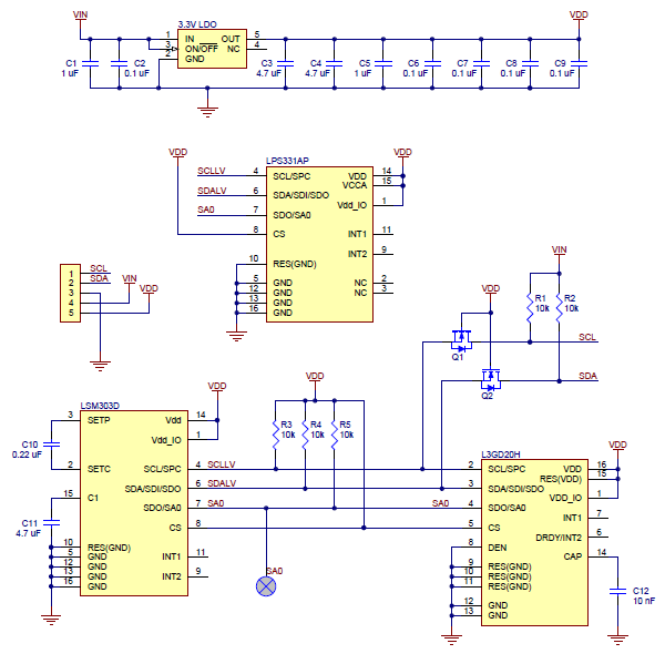 |
The above schematic shows the additional components the carrier board incorporates to make the LPS331AP, L3GD20H, and LSM303D easier to use, including the voltage regulator that allows the board to be powered from a single 2.5 V to 5.5 V supply and the level-shifter circuit that allows for I²C communication at the same logic voltage level as VIN. This schematic is also available as a downloadable pdf: AltIMU-10 v3 schematic (207k pdf).
I²C Communication
The LPS331AP’s barometer, the L3GD20H’s gyro, and the LSM303D’s accelerometer and magnetometer can be queried and configured through the I²C bus. Each of the four sensors acts as a slave device on the same I²C bus (i.e. their clock and data lines are tied together to ease communication). Additionally, level shifters on the I²C clock (SCL) and data lines (SDA) enable I²C communication with microcontrollers operating at the same voltage as VIN (2.5 V to 5.5 V). A detailed explanation of the protocols used by each device can be found in the LPS331AP datasheet (453k pdf), the L3GD20H datasheet (3MB pdf), and the LSM303D datasheet (1MB pdf). More detailed information about I²C in general can be found in NXP’s I²C-bus specification (371k pdf).
The L3GD20H, LSM303D, and LPS331AP each have separate slave addresses on the I²C bus. The board connects SA0 pins of the three ICs together and pulls them all to VDD through a 10 kΩ resistor. You can drive the SA0 pin low to change the slave address. This allows you to have two AltIMUs (or an AltIMU v3 and a MinIMU v3) connected on the same I²C bus. The following table shows the slave addresses of the sensors:
| Sensor | Slave Address (default) | Slave Address (SA0 driven low) |
|---|---|---|
| L3GD20H (gyro) | 1101011b | 1101010b |
| LSM303D (accelerometer and magnetometer) | 0011101b | 0011110b |
| LPS331AP (barometer) | 1011101b | 1011100b |
All three chips on the AltIMU-10 v3 are compliant with fast mode (400 kHz) I²C standards as well as with the normal mode.
Sample Code
Pololu have written a basic LPS331 Arduino library, L3GD20 Arduino library, and LSM303 Arduino library that make it easy to interface the AltIMU-10 v3 with an Arduino or Arduino-compatible board like an A-Star. They also make it simple to configure the sensors and read the raw pressure, gyro, accelerometer, and magnetometer data.
For a demonstration of what you can do with this data, you can turn an Arduino connected to a AltIMU-10 v3 into an attitude and heading reference system, or AHRS, with this Arduino program. It uses the data from the AltIMU-10 v3 to calculate estimated roll, pitch, and yaw angles, and you can visualize the output of the AHRS with a 3D test program on your PC (as shown in a screenshot above). This software is based on the work of Jordi Munoz, William Premerlani, Jose Julio, and Doug Weibel.
Protocol Hints
The datasheets provide all the information you need to use the sensors on the AltIMU-10 v3, but picking out the important details can take some time. Here are some pointers for communicating with and configuring the LPS331AP, L3GD20H, and LSM303D that Pololu hope will get you up and running a little bit faster:
- The pressure sensor, gyro, accelerometer, and magnetometer are all off by default. You have to turn them on by setting the correct configuration registers.
- You can read or write multiple pressure sensor, gyro, or accelerometer registers in a single I²C command by asserting the most significant bit of the register address to enable address auto-increment.
- Compared with previous LSM303-series sensors, the register interface to the magnetometer in the LSM303D is much more consistent with the accelerometer interface, and its accelerometer and magnetometer share a common I²C address instead of acting as two separate slave devices on the same bus.
- The pressure sensor has a 24-bit pressure reading. The gyro, accelerometer, and magnetometer all output readings in a 16-bit reading (obtained by combining the values in two 8-bit registers for each axis).
Product Comparison
we carry several inertial measurement and orientation sensors. The table below compares their capabilities:
| Product Name | Sensors | Estimation | Other | ||||||
|---|---|---|---|---|---|---|---|---|---|
| Gyros (3x) | Accels (3x) | Mag (3x) | Altitude | Roll | Pitch | Yaw | Quaternion | Enclosure | |
| Pololu MinIMU-9 v3 |  | | | ||||||
| Pololu AltIMU-10 v3 | | | | | |||||
| CHR-UM6-LT Orientation Sensor | | | | | | | | ||
| CHR-UM6 r2 Orientation Sensor | | | | | | | | | |
Exact shipping can be calculated on the view cart page (no login required).
Products that weigh more than 0.5 KG may cost more than what's shown (for example, test equipment, machines, >500mL liquids, etc).
We deliver Australia-wide with these options (depends on the final destination - you can get a quote on the view cart page):
- $3+ for Stamped Mail (typically 10+ business days, not tracked, only available on selected small items)
- $6+ for Standard Post (typically 6+ business days, tracked)
- $10+ for Express Post (typically 2+ business days, tracked)
- Pickup - Free! Only available to customers who live in the Newcastle region (must order online and only pickup after we email to notify you the order is ready). Orders placed after 2PM may not be ready until the following business day.
Non-metro addresses in WA, NT, SA & TAS can take 2+ days in addition to the above information.
Some batteries (such as LiPo) can't be shipped by Air. During checkout, Express Post and International Methods will not be an option if you have that type of battery in your shopping cart.
International Orders - the following rates are for New Zealand and will vary for other countries:
- $11+ for Pack and Track (3+ days, tracked)
- $16+ for Express International (2-5 days, tracked)
If you order lots of gear, the postage amount will increase based on the weight of your order.
Our physical address (here's a PDF which includes other key business details):
Unit 18, 132 Garden Grove Parade
Adamstown
NSW, 2289
Australia
Take a look at our customer service page if you have other questions such as "do we do purchase orders" (yes!) or "are prices GST inclusive" (yes they are!). We're here to help - get in touch with us to talk shop.
Have a product question? We're here to help!
Guides

The Maker Revolution
Projects

Days2Bin: Pico Powered Bin Reminder

Raspberry Pi Video Looper Display Installation | Overshare Video Festival

Mailbox Delivery Notification System

Makers love reviews as much as you do, please follow this link to review the products you have purchased.
Product Comments