If you’ve ever built a robot with wheels, or any motorised parts really, you’ll have come across the issue of needing to drive it from your microcontroller. Because a standard chip is only able to output a small amount of current, you’re not able to reliably drive small motors directly, let alone bigger ones. So, you need a way to drive them, which is where a motor driver comes in.
A motor driver uses a larger chip or discrete FETS which are able to handle larger amounts of current and higher voltages than the standard 5V/3.3V from a microcontroller pin. They allow you to control a much larger load, from a small signal. It’s important to note that when referring to motor drivers and controllers, the type of motor also has to be taken into account. A brushed DC motor is the simplest to control as there’s no timing or protocol required, whereas stepper and servo motors both require a specific type of signal to operate them correctly. For simplicity’s sake, we’ll use examples that are designed for simple, brushed motors, however, the principle applies to all types.
A common question which is raised by those diving into robotics for the first time is ‘what’s the difference between a motor driver and a motor controller?’ The TLDR is that a motor driver simply handles the power to drive the motors, whereas the logic and digital control has to be done by an external microcontroller or microprocessor, whereas a motor controller has all of the logic circuitry built in and can be controlled by a higher-level interface such as a PWM signal, USB, analogue input etc…
So that’s the TLDR, but what about a more in depth look? Well, let’s start by looking at how the most common form of motor speed control works; the H-bridge.
 Motor Drivers
 Motor Drivers
As mentioned, an H-bridge is the most common way to drive a brushed DC motor, and its operation is quite simple. It uses two pairs of transistors (usually MOSFETS) to control the direction that current is allowed to flow through the motor. By changing the direction of the current flow (reversing the voltage across the terminals), the direction of rotation will change. Because brushed motors play nicely with PWM control, speed, as well as directional control, is enabled by pulsing the MOSFETs to drive them. The MOSFETs (or FETs for short) are just acting as switches, so if you’re trying to wrap your head around that, just think of them as simple on/off switches. I’ve included the four diodes often used in H-bridge designs as they are important to protect against voltages produced by the motor as it turns. Don’t worry too much about this, but keep them in mind if you plan on building your own. This’ll make more sense with a schematic of an H-bridge, so let’s take a look:
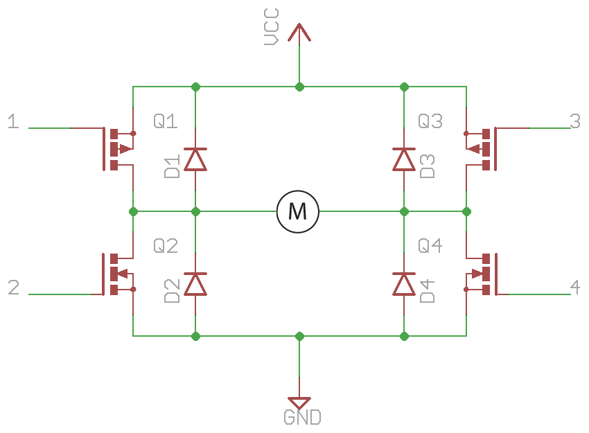
As you can see, there are four FETs which handle the switching. These may need to be driven by smaller transistors depending on the model, and additional components such as resistors have been left out to make it easier to read.
Directional Control
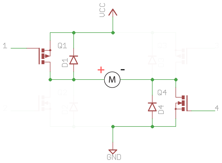
To turn the motor in one direction, two of the FETs need to be turned on in the following fashion. This allows a current to flow through the motor, and creates motion:
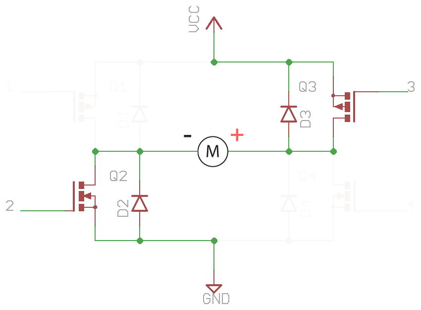
To turn the motor in the other direction, the opposite pair of FETs are turned on (and the others turned off), reversing the direction of current flow:
As mentioned earlier, speed control can be implemented by pulsing the FETs using PWM which causes them to switch on and off rapidly. Because a motor is a slave to the laws of physics (as we all are), the spinning rotor has enough momentum that it’s inertia keeps it spinning when the FETs are turned off, and the result is that it averages out the speed of the PWM duty cycle. To learn more about PWM, take a look at our All About LEDs tutorial.
Braking
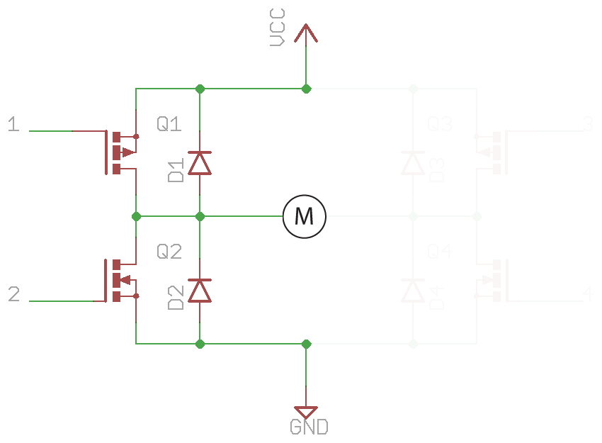
If you want the motor to stop turning, you can, of course, turn off all of the FETs which will completely disconnect the motor from power. However, the motor still has momentum, so it will gradually come to a complete stop. If you want to suddenly stop the motor, you can apply an equal voltage to both sides, known as braking:

There is a use-case that should be avoided at all times; that is, turning on one side of the H-bridge, which will create an almost direct path from the voltage supply to ground. This will short out your circuit and damage components, batteries, anything in the circuit. There’s only one side shown below as an example, but the same would hold true for the other side, and if all four were turned on at once:
So, there’re a few more hidden details which need to be accounted for when designed an H-bridge motor driver, but that’s the general concept, and it’s how most motor drivers work. As you can see, digital logic, timing functions, and safeguards need to be implemented to control the motor driver, but the hardware can be interfaced fairly easily to a microcontroller.
Of course, you don’t have to build your next motor driver out of discrete components (although it can be a great project to learn about it, and also if you have some niche specs). There are motor driver chips readily available to drop into your PCB, and also ready-to-go breakout boards and modules which you can wire into your projects. Here are some of our favourites:
- Adafruit Motor/Stepper/Servo Shield for Arduino
- DRV8833 Dual Motor Driver Carrier
- Monster Moto Shield
Motor Controllers
 Motor Controllers
This section will be a little shorter than the last, as building on top of a motor driver is just a matter of adding a digital harness to control the driver, and implementing an interface for control. Motor controllers will have one or more of the following inputs:
- PWM
- Analog signal
- USB
- Serial (I2C, SPI, etc…)
- UART
- RC (hobby radio)
So the idea of a motor controller is that you can just wire up your motor and power supply, drop the controller into an existing project, and communicate with it as easily as the protocol allows for. Digital communication with a motor controller even allows for feedback data such as current measurement and error detection.
Motor controllers with USB support allow you to control a motor directly from a USB host such as a computer! The software/protocol will depend on the board itself with each brand being different, but it's pretty cool. So all you need to control a motor driver is a device which can communicate with it via the methods that are supported by the controller board.
Because of the additional circuitry integrated into motor controllers, they are a more expensive option, but if you just want an add-on style board, then they’re perfect.
Here’re a few of our Maker Favourite motor controllers:
- Jrk 12v12 USB Motor Controller with Feedback
- Jrk 21v3 USB Motor Controller with Feedback
- Simple Motor Controller 18v7
Matching Specifications
One last thing to be aware of which is important for both motor drivers and controllers, is making sure that they match the electrical specifications of the motor. For example, some motors, and quite small, and only designed for toys and driving light loads. These don't draw too much current and will usually at lower voltages (less than 12V). Larger motors which can drive larger loads are capable of drawing much larger currents, especially during stall or startup conditions, often at voltages equal to or greater than 12V. You need to make sure that both the current (allowing for peak surges) and voltage ratings of your driver/controller are greater than that of your motor.
Which One is Right For You?
Hopefully, that gives you some insight into the differences between motor drivers and motor controllers and gets you on the way to adding motion to your next project. As far as which one is going to be the best fit for your project, only you can make that decision, but here are a few points to consider:
- Motor controllers require little consideration for ensuring it will work as intended. Provided you can communicate with it, you can use it.
- Motor drivers require more thought when implementing as you need to create software (or hardware) functions to drive the FETs correctly, ensure that incorrect control signals aren't given that could result in shorts, etc...
- Motor drivers are usually cheaper than controllers as they're simpler devices.
- Motor controllers provide feedback, error detection, and other features which usually aren't found on basic motor driver boards.
- A plain old motor driver can allow you to control exact how the motor is driven, and allows for a greater scope in development.

