So you’ve got your Raspberry Pi. You’ve gotten NOOBS setup on it, explored Raspbian a bit, and you’re feeling like a bit of a pro. Awesome! Now let’s get down to the nitty gritty side of things, what it’s all about, GPIO pins.
GPIO stands for General-Purpose-In/Out and is the gateway between your Raspberry Pi, and the world. Whilst plugging in a display, keyboard/mouse, and exploring around the software can be fun, the real excitement comes from connecting up sensors, buttons, motors, lights, anything you can think of can generally be connected up to the Raspberry Pi, one way or the other.
Today we’re going to embark on a multi-part tutorial which will get you using programming buttons, LEDs and sensors using Python (don’t worry, we’ll walk you through it step by step).
We’ll be using the Raspbian GUI (Graphic User Interface) for this tutorial, if you don’t have it installed on your SD card, check out our Setting up NOOBS tutorial to get that setup.
To write and execute code in Python, we need to use the Python text editor, and the Python shell. The text editor is where we write our code, and then we use the Python shell to run it and use console features like print readouts.
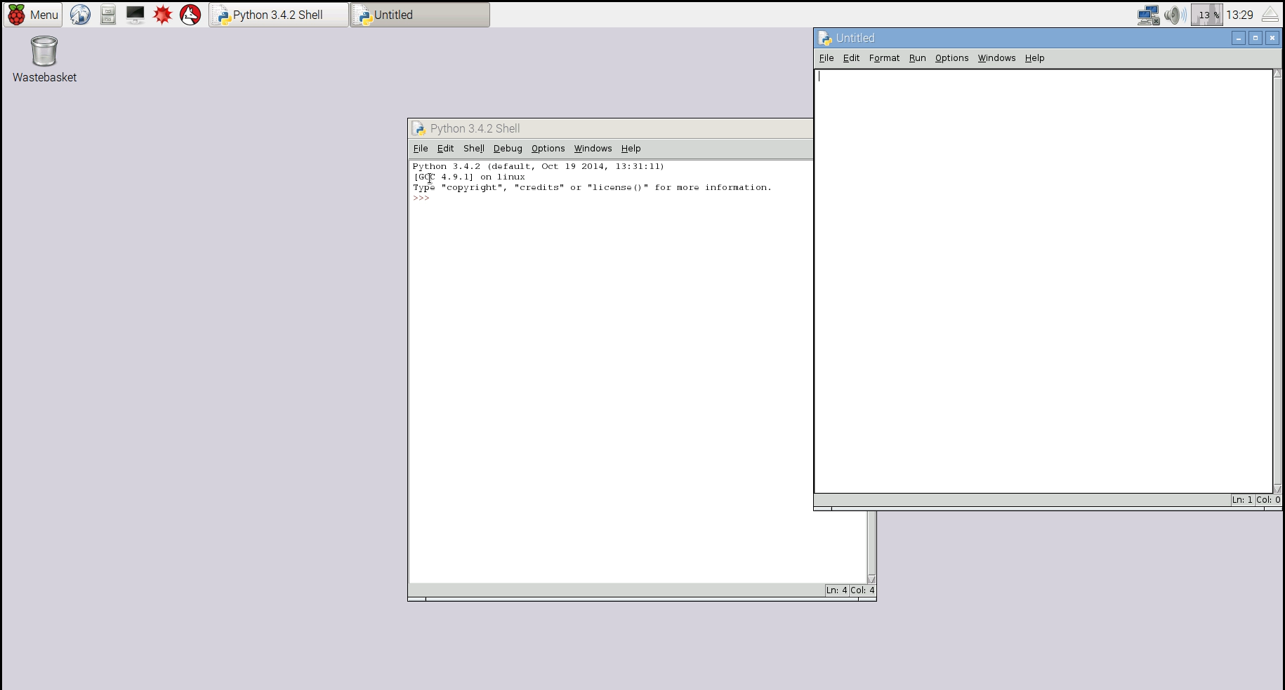
Let’s go ahead and open up a new project in Python by going to Menu – Programming – Python 3 (IDLE). The Python 3.x.x Shell should open, and then we go to File – New File. This will open up our Python text editor. Got there? Good job. Now before we can program anything we need two essential elements, an input, and an output.
To get our feet wet with GPIO and Python we’re going to make a simple circuit that we can build on later in the tutorial.
No prior knowledge of Python or programming is required to complete this project, however we recommend that you read our ‘Welcome to Analog Electronics’ tutorial first, as this tutorial won’t go into the circuitry in depth.
The Gear
- Raspberry Pi (any model should be fine, however we are using a Pi 3)
- Breadboard (we chose to use a cute little 400 tie point board, but any will do
- Jumper Wires
- Resistor Kit
- Tactile Switch
For most builds, I prefer to use male-female jumper wires to go straight from the GPIO pins to the breadboard and the Pimoroni PiBow Coupe case which has fantastic pinout labels.
You can also use a breakout board like the Adafruit Cobbler to connect to the GPIO pins to your breadboard, however you will need to cross-match the printed pin labels to the GPIO numbers.
However you connect your Raspberry Pi, make sure that your Raspberry Pi is disconnected form the power supply as the onboard Broadcom chip has limited protection circuitry and is quite sensitive to static and power supply shorts.
Make Sure You Have The Latest RPi.GPIO Module
In order for the code to perform as intended, you should have the latest version of the RPi.GPIO module. At the time of publication 0.6.2 is the latest version. To check what version you have, go to the Terminal and type:
sudo python
import RPi.GPIO as GPIO
GPIO.VERSION
If you don’t have the latest version don’t worry, it’s easy to update by going into your Terminal and typing:
sudo apt-get update
# Let things run their course here before typing the next command, it may take a while
sudo apt-get dist-upgrade
Let’s press on and build a simple pushbutton and LED circuit that we can use to program in Python.
The Goal
By the end of this article, we will have a circuit with a pushbutton that can control the colour of an RGB LED, and print the colour to the console.
But like any good design, we’ll build, and test it in smaller modules as we go.
The Circuit

So what’s going on in this circuit we’ve just built? We’re using a common anode RGB LED with 220 Ohm current limiting resistors to pins 2, 3, 4. Then we have a tactile switch that when pressed, will pull pin 6 low via a 10K current limiting resistor. The current limiting resistor here is super important, otherwise you will be shorting 3.3V straight to ground, which could fry your board. Finally we are connecting 3.3V and Ground from the GPIO power pins. Anyway, that’s the circuit, now let’s tell it do something!
Flash (aaaaaah) – Part 1
# Import Modules
import RPi.GPIO as GPIO

# Pin Definitions
led = 2
button = 5

#GPIO Setup
GPIO.setmode(GPIO.BCM) # Set pinouts to Broadcom numbering
GPIO.setwarnings(False) # Disable GPIO warnings
GPIO.setup(button, GPIO.IN, GPIO.PUD_UP) # button set as input with pullup resistor
GPIO.setup(led, GPIO.OUT) # led set as output

# Main Loop
try:
    while True:
		buttonState = GPIO.input(button) # Read button input
		GPIO.output(led, buttonState) # Output buttonState input to led pin

except KeyboardInterrupt: # Detect if Ctrl   C is pressed which will exit the program cleanly
	GPIO.cleanup()
	print("Program Exited")
So what’s going on here exactly?
The lines preceded by a ‘#’ symbol are comments, so go ahead and read through the code, and it should make a bit of sense, don’t worry if you don’t get it all, plenty of time for you to master the language of Python.
Once you’ve got a bit of a handle on what’s happening, I encourage you to type out the code yourself the code into your text editor rather than just copy it as it will help you familiarize yourself with the language.
Now, hit F5, it will prompt you to save your program, then it will run in the Python shell. If everything has gone according the plan, when you press the button, the LED should light up! Enjoy that deep seated feeling of contentment at running your first Python program!
At this point I can hear you saying ‘I don’t need a microcontroller just to do that, what’s the point?’ and you’re right, that isn’t an overly clever use of the Raspberry Pi, let’s make it do something more interesting!
RGB Toggle – Part 2
Wouldn’t it be great, if we could toggle the LED on/off with our button, rather than needing to hold it in? Well we can do just that, and while we’re at it, cycle through the different colours of our RGB LED.
# Import Modules
import RPi.GPIO as GPIO
import time

# Pin Definitions
ledR = 2
ledG = 3
ledB = 4
button = 5

# Variable Declarations
buttonCount = 0
lastButtonState = 1
lastButtonPress = 0

# GPIO setup
GPIO.setmode(GPIO.BCM)
GPIO.setwarnings(False)
GPIO.setup(button, GPIO.IN, pull_up_down=GPIO.PUD_UP)
GPIO.setup(ledR, GPIO.OUT)
GPIO.setup(ledG, GPIO.OUT)
GPIO.setup(ledB, GPIO.OUT)

# Init setup
GPIO.output(ledR, 1)
GPIO.output(ledG, 1)
GPIO.output(ledB, 1)

# Main Loop
try:
    while True:
        buttonState = GPIO.input(button) # Read button input and store it as buttonState
        if buttonState == 0 and lastButtonState == 1 and (time.time() - lastButtonPress) > 0.05: # Detect falling edge and debounce
            lastButtonPress = time.time() # record the time that the button was pressed for debounce
            buttonCount = buttonCount   1 # Everytime button is pressed, add 1 to the buttonCount
            lastButtonState = 0

            if buttonCount == 4: # Rest the buttonCount to 0 once it has reached 3
                buttonCount = 0

            if buttonCount == 0: # off state
                GPIO.output(ledR, 1)
                GPIO.output(ledG, 1)
                GPIO.output(ledB, 1)
                print("I am Off")

            if buttonCount == 1: # Red state
                GPIO.output(ledR, 0)
                GPIO.output(ledG, 1)
                GPIO.output(ledB, 1)
                print("I am Red")

            if buttonCount == 2: #Green state
                GPIO.output(ledR, 1)
                GPIO.output(ledG, 0)
                GPIO.output(ledB, 1)
                print("I am Green")

            if buttonCount == 3: # Blue state
                GPIO.output(ledR, 1)
                GPIO.output(ledG, 1)
                GPIO.output(ledB, 0)
                print("I am Blue")

        if buttonState == 1 and lastButtonState == 0: # Button release
            lastButtonPress = time.time() # Recrod button release time for debounce
            lastButtonState = 1

except KeyboardInterrupt: # Exit event
    GPIO.cleanup()
    print("Program Exited")
Once again, have a read through the code and the comments to get a general understanding of what’s going on. We’ve included features such as debouncing using the ‘time’ module.
Now write the code into your own text editor and your LED should cycle through Red, Green, Blue, off, and then print ‘I am ‘colour’’ in the shell.
Schweeeeet! You’ve now written two codes in Python, and learnt how we can use the GPIO pins to send and receive information.
To read through the RPi.GPIO module documentation, click here.

