Welcome to the Sparkfun Inventors Kit (SIK) Ver 4.0 tutorial page. In this beginner’s tutorial, we will explore the basics of microcontroller programming and circuit electronics through a series of projects that are provided in the Sparkfun Inventors Kit Guide. These projects are within the scope of light, sound, motion, and robotics with electrical and electronic terms and ideas explained along the way. The videos in this tutorial will explore common problems that a new maker may face in their travels with a step-by-step walkthrough layout. With all that said, let’s get to assembling and installing your complete RedBoard setup!
If you encounter any problems throughout this tutorial, then please head to our forum. As full-time makers ourselves, we are here to help and have no doubt come across the same or similar issues along our electronic travels.
Assembling the Baseplate

Before we get to building the circuits contained in the manual, we must first assemble the baseplate. The assembly process is quite simple:
- Remove the Baseplate, RedBoard, Screws, and Breadboard from the SIK box.
- Remove the adhesive covering from the back of the Breadboard and place it in the dedicated section (flat part) of the baseplate.
- Screw the RedBoard into the Baseplate via the allocated holes present in the board – make sure the screws aren’t too tight, they’re there to limit movement only.

RedBoard Anatomy
The RedBoard from Sparkfun is a variation of the Arduino Uno R3 with an ATMega328 microprocessor at its core, a 16Mhz crystal oscillator and a Mini-USB connector for uploading code and serial communication. A visual breakdown of the board appears below and the ATMega328 datasheet can be found here.
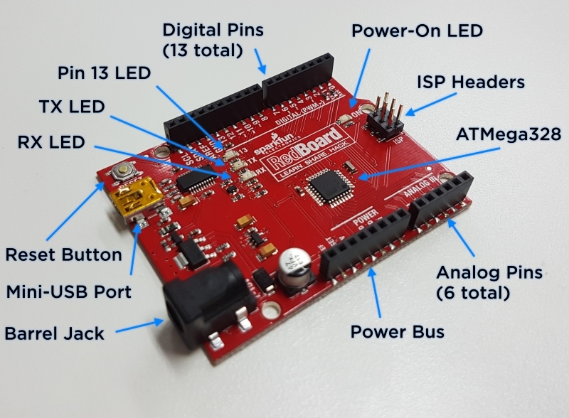
Labeled above are:
- 13 I/O Digital Pins
- 6 Analog Input Pins
- Power Bus
- TX, RX, Pin 13 and Power-ON LED
- ATMega328 Microprocessor
- Mini-USB Port
- Barrel Jack connection
- Reset Button
- ISP Headers
Breadboard Anatomy
The prototyping breadboard provided in the Sparkfun Inventors Kit is where the physical connections of the electrical components will happen, hence understanding how it works is very important. The breadboard has 4 power rails (2 +ve and 2 -ve) which run the length of the board. Without an external power supply (from the Power Bus on the RedBoard or otherwise) they will have no electrical potential. The center rows are isolated in a perpendicular fashion to the power rails with an insulator rail running down the center of the board separation column e from column f.

Installing the Arduino IDE
To get started with the projects we need to install the program that will allow us to upload our code to the RedBoard. This program is called the Arduino Integrated Development Environment or, more simply, the Arduino IDE; it can be found from “arduino.cc/downloads” under the 'Windows Installer' section.

Click on ‘JUST DOWNLOAD’ for a free download of the IDE and an executable file (.exe) should download. Follow the installation process making note of where the program is being installed to (this is important for the next step).
It may be helpful to download the Sparkfun Inventor Kit code for some of the larger projects. This can be found at “sparkfun.com/SIKcode”.
Connecting the RedBoard to the Computer
Use the provided USB cord to connect the Mini-USB port of the RedBoard to your computer. After the RedBoard is connected, open the device manager on your computer (this is done by pressing the windows key and then typing in “device manager”). Find the label ‘Other Devices’, then right click on the ‘USB Serial Port’ label found within it. Select properties, then driver details, then browse my computer for driver software and then paste into the directory that you saved the Arduino IDE. An example of this is: “C:\Program Files(x86)\Arduino\drivers\FTDI USB Drivers”

A successful upload will result in a new label, ‘Ports (COM & LPT)’, with the board being labeled ‘USB Serial Port (COMXX)’ where ‘XX’ is the associated COM Port for the RedBoard. Take note of the COM Port the RedBoard is registered to as it’s important for the IDE part of the setup task.
If unsuccessful, consult our forum and we’ll step through it together.
Open the Arduino IDE that we downloaded earlier, if your setup settings were left as default there should be a shortcut on your desktop. Across the top of the IDE there is a ‘Tools’ tab which, upon pressing, will drop down presenting more labels beneath it. Select the ‘Board:’ label and make sure that the ‘Arduino/Genuino Uno’ option is selected. Re-click on the ‘Tools’ tab and then select the ‘Port:’ label; the COM Port for your RedBoard should appear and be selected.
An Explanation of the Arduino IDE User Interface
The Arduino IDE is where the programming magic will happen. It’s the powerhouse that compiles and uploads your code to the RedBoard for use and where serial communication is operated from. At the top is the name of the Arduino ‘Sketch’ along with the program version. A Sketch’s default name is the date with a,b,c,… following depending on the amount you’ve made that day. Underneath that is the Toolbar Ribbon that contains all the different commands you’ll need when completing the projects in this Guide. The File tab contains commands like save, load, new and preferences. The Edit tab contains commands like copy, paste and font sizing. The Sketch tab contains verify, upload, add libraries. Tools contain the serial monitor, port and board selector and finally, the help tab contains general help commands. The Frequent Commands Ribbon is situated below the Toolbar Ribbon and, you guessed it, contains commands that are used more frequently than others. The Coding Area is where the programs to be uploaded are written with the Message Area and Debug Window displaying the current status of, and outcome of that process. Finally, there is the Connection area which displays the Port and Board connected to the computer.

Now that you've installed the IDE and RedBoard drivers it's time that we jump into our first Project Set! Light!
For the next Sparkfun Ver4.0 tutorial on Project Set 1, click here.

