Hello there, how’s your day been? Good? Fantastic! Not so good? Don’t worry it’s about to get a lot better, because today we’re going to take a look at how to use the I2C interface on our Raspberry Pi to control I2C devices.
What is this “I2C” you may ask? I2C is a serial communication protocol originally developed by Philips Semiconductor to enable simple low level communication between chips. It is now a communication standard in the computing world for sensors, microcontrollers, port expanders and more.
Before we dive into using the I2C interface on our Raspberry Pi, take a look at the fantastic explanation of how the I2C protocol works in the I2C with Arduino article. The first section is generic to I2C and doesn’t just apply to Arduino.
The Raspberry Pi is a fantastic piece of hardware which allows for all kinds of different software and hardware applications, but one of the draw backs is the limited number of GPIO pins. The original Raspberry Pi board had even less, only 26, which includes the power supply pins, and whilst the 40 GPIO pins provided on all current models of Pi is a step forward, it can still be quite limiting.
To get started with I2C we’re going to expand the GPIO pins available by using the MCP23017 16 Bit I/O Expander. This chip gives us an extra 16 in/out pins to use for whatever you like! Since I2C only requires two wires for communication, port expanders like the MCP23017 are a fantastic way to greatly expand the capabilities of any board. Because the I2C protocol allows for multiple slave devices we aren’t just limited to using one MCP23017 chip on our I2C bus, we can use up to 8 MCP23017 on a single bus for a maximum of 128 digital I/Os of just 2 control wires! Digital electronics is very cool.
Due to the popularity of the Raspberry Pi platform, people have written modules designed to make common applications easy to do inside of Python and the MCP23017 is no exception, there are quite a few modules that are designed to make using the MCP23017 as easy to use as a standard GPIO pin. Sound good? It does, there are a few issues with this approach however:
- Each module is going to require different syntax, a different installation method, and have its own learning curve.
- As modules get more and more specific, it gets harder and harder to provide support for them and guarantee their use.
- Whilst using a module to do everything for you can be great, it doesn’t give you the opportunity to learn how the device works, or gain confidence with its functionality.
For this reason we’re going to use the SMBus module to control our MCP23017. The SMBus module takes care of handling the protocol specifics such as acknowledge bits, start stop bits, and other things that can make our code bloated, and it allows us just to send data bytes straight to an I2C device. This gives us the experience of learning how to use the MCP23017 and other devices, but doesn’t bog us down in the nitty gritty aspects.
The Gear
To follow this tutorial you will require the following components:
- Raspberry Pi 3
- MCP23017
- Male-Male Jumper Wires
- Female-Male Jumper Wires
- 16x 330 Ohm Resistors (we recommend the Sparkfun Resistor Kit)
- 2x 4.7K Ohm Resistors
- 8x Blue 5mm LEDs (our 50 piece, 5 colour LED pack is perfect)
- 8x Red 5mm LEDs
Along with this things, you will need everything required to use the Pi 3 board such as a power supply, display etc… for more info on this, check out our Hello World with Raspberry Pi tutorial. As always, we strongly recommend using the Pimoroni Pibow Coupe case. The hardware access and pin labelling will change your life
The Goal
To get our feet wet with I2C we’re going to create a dual 8 bit binary counter using LEDs. This is a fun little project that will count through from 0-255 in binary.
Raspberry Pi Board Setup
Before we do anything though, we need to do a few things to setup our Raspberry Pi board to work with the I2C interface. Make sure that you follow the steps below EXACTLY as they are listed, and if you run into issues at the end, it can help to freshly install Raspbian and then try again.
The very first thing to do is make sure that Raspbian is updated to the latest version. To do this, open a new Terminal windows and type:
sudo apt-get update
And after the update is completed:
sudo apt-get upgrade
Awesome, now you Raspberry Pi will have all of the latest packages available to use. Now we need to enable the I2C interface on our board. To do this, go to the Menu -> Preferences -> Raspberry Pi Configuration, then under the ‘Interfaces’ tab, select I2C as ‘enabled’, and then reboot.
Now we will install a set of tools which will take care of the I2C handling. SMBus is a python module which makes it super easy to write date on the I2C bus, and I2C Tools which allows us to control the I2C interface via the Terminal.
Go to your Terminal window and type:
sudo apt-get install python3-smbus i2c-tools
Follow the prompts, and when the installation has finished, restart your Pi. Your Pi should now be setup to use the I2C interface in Python 3 and Terminal.
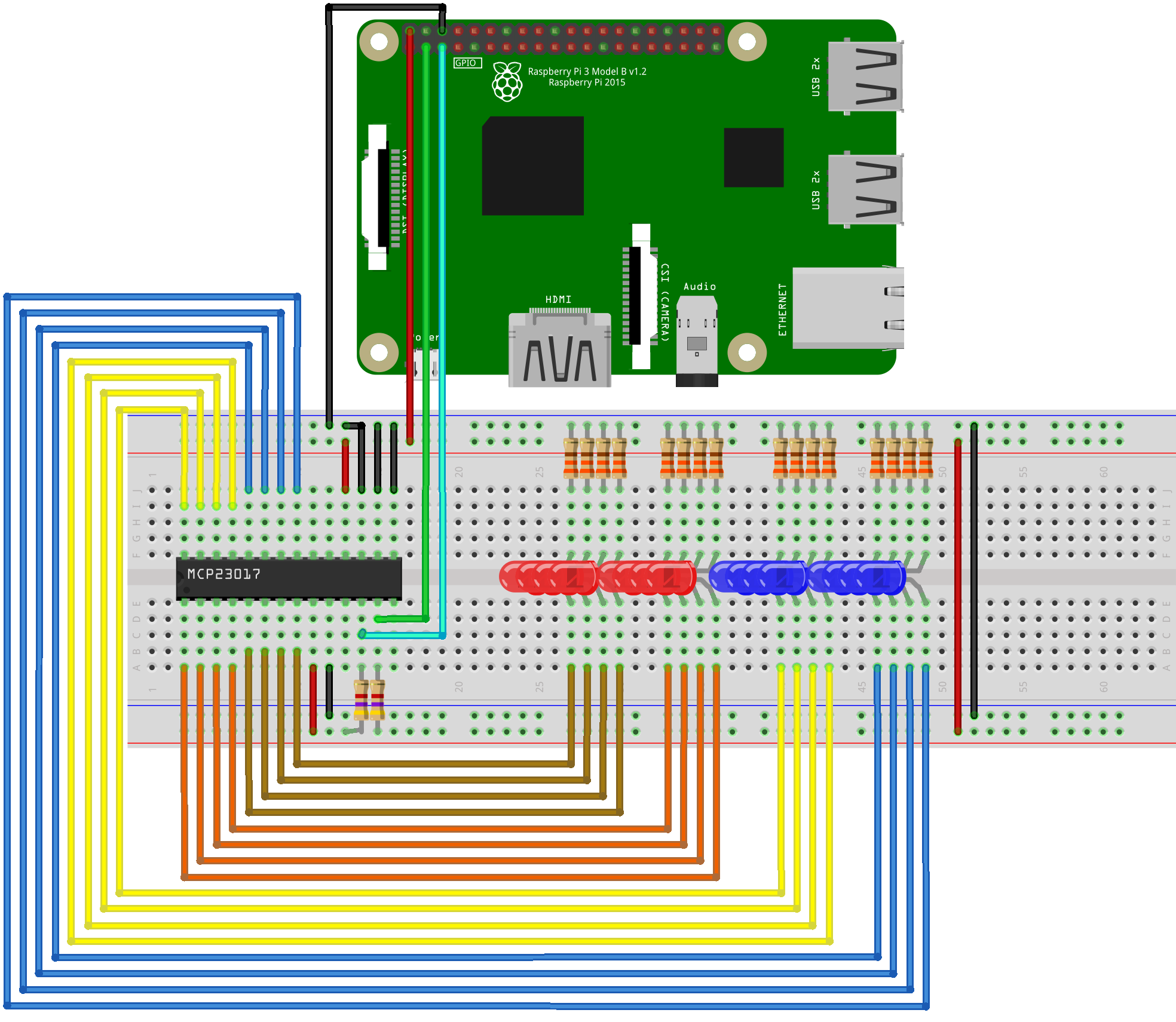
The Circuit
Now that our Raspberry Pi board is setup to communicate using the I2C interface, let’s build the circuit that we’ll be using to use the MCP23017. Before you do anything with the GPIO header though, make sure that your Raspberry Pi board is turned off and unplugged from power.
You can find the pinout for the Raspberry Pi's I2C bus pins (and every other interface) at pinout.xyz
We’re using 16 LEDs each connected to a separate I/O pin of the MCP23017 to display the state of each pin. It is important that we use the 5V output of the Pi to power our circuit because whilst the MCP23017 can run on 3.3V, the 3.3V pin on the Pi cannot supply enough current for 16 LEDs.
Using the MCP23017
Now that our Raspberry Pi board is setup to communicate using the I2C interface, we’re going to test it out using simple Terminal commands before writing anything in Python. This will allow you to understand how the MCP23017 registers work, one line at a time, before writing a program to control it in a more complex way.
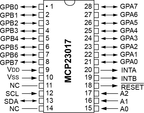
As mentioned in the linked article above, an I2C slave device has a unique 7 bit address which can be used to access the device. The MCP23017 has 4 of these bits hard coded to each device that we can’t change, the other 3 bits are definable by the hardware address pins on pins 15, 16 and 17, and by connecting these to either our supply voltage (high) or ground (low) we can set a unique address for this device. If you’ve followed our wiring diagram correctly, all three pins should be connected to ground, giving our MCP23017 a binary address of (0010000x). The ‘x’ is the extra Read/Write bit to complete the other 7 address bits (making 1 byte) which we set depending on whether we want to read or write (for help understanding hexadecimal numbers, check out our Numbers in Hex, Binary, and Decimal article.
We can check for any devices on the I2C bus using the command in a Terminal window:
i2cdetect -y 1
If you've wired everything up correctly, the response should look like this:
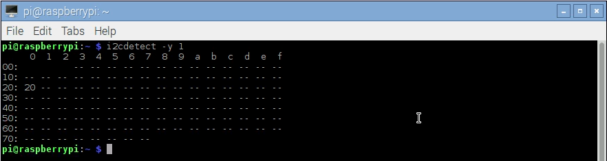
This tells us that the address of the MCP23017 is 0x20, as we expected.
The MCP23017 assigns its 16 I/O pins into two 8 pin directories which are both written to using separate registers.
Communicating with the MCP23017 is fairly easy once you break it down. To we communicate with the device in a packet consisting of 3 bytes (3 lots of 8 bits).

*Note that the SMBus module is taking care of all the timing and nitty-gritty details required to send data on an I2C bus, this allows us to only focus on the data we’re sending*
The first byte is the 7 bit address and the last bit is either a 1 to read, or a 0 to write.
The second byte is the register that we want to access. In this tutorial we will be accessing 4 different registers:
- 0x00 tells the device that we want to change the mode (input or output) for the pins in directory A
- 0x01 tells the device that we want to change the mode (input or output) for the pins in directory B
- 0x12 tells the device that we are writing to the pins in directory A
- 0x13 tells the device that we are writing to the pins in directory B
The third byte is used to access each pin of the directory we have specified.
Now that we understand how to use the I/O pins on the MCP23017, let’s go into the terminal to try using them as outputs.
-i2cset -y 1 0x20 0x00 0x00Open a new Terminal window and type in the following:
This will put all 8 pins in IODIRA (I/O directory A) in output mode.
Then type:
-i2cset -y 1 0x20 0x12 0xff

This will turn on all 8 LEDs in directory A. If you convert the hex numbers into binary for the third byte, 0xff is 11111111. Now imagine each one of those bits controls the on/off state for each of the 8 pins. So if you wanted to only turn on the first 4 LEDs, your byte would be 00001111 which is 0x0f in hex. Once you've got them all to light up, try turning them all off. *Hint, use the hex value for 00000000*
Play around with writing different combinations of LEDs high and low using the registers listed above, and once you have a handle on how to communicate with the MCP23017, let’s move on to creating our binary counter in Python.
The Code
The code to create our dual binary counter is incredibly simple. Take a look through the comments in the code to understand what each line does, and then feel free to create different combinations of LED patterns.
It is import to note that since we installed the SMBus module for Python3, you will get an error for a missing module if you try to run this code in Python 2. Because python 2 is only really supported for legacy reasons, there is no reason to use it for any new projects.
Run the code by going to Run -> Run Module (F5).
#import modules
import smbus
import time

#setup SMBus
bus = smbus.SMBus(1)

bus.write_byte_data(0x20, 0x00, 0x00)
bus.write_byte_data(0x20, 0x01, 0x00)

#initialise counter
counter = 0

#main loop
try:
    while 1:
        for counter in range(0, 255):   #the counter variable increments by 1 through to 255, then loops back to 0
            bus.write_byte_data(0x20, 0x12, counter)    #write the value of counter IODIRA
            bus.write_byte_data(0x20, 0x13, counter)    #write the value of counter IODIRB
            time.sleep(0.5)    #wait for 500ms, alter this time to increase/decrease the speed of the counter

except KeyboardInterrupt:   #when Ctrl   C is pressed, write all the LEDs off
    bus.write_byte_data(0x20, 0x12, 0x00)
    bus.write_byte_data(0x20, 0x13, 0x00)
    print("Program Exited Cleanly")
What Now?
Awesome sauce, you’re now a bit of a pro. The MCP23017 can be used for much more than just turning LEDs on and off, it’s pins can be used as inputs as well, with versatile interrupt options, plus you can daisy chain multiple chips to get even more pins just using the I2C bus.

