
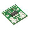
ACS709 Current Sensor Carrier -75A to +75A
Available with a lead time
Expect dispatch between Apr 25 and Apr 29
Quantity Discounts:
- 10-25 $24.60 (exc GST)
- 25+ $24.09 (exc GST)
 |
This current sensor is a carrier board or breakout board for Allegro’s ACS709LLFTR-35BB-T Hall effect-based linear current sensor with overcurrent fault output; Pololu therefore recommend careful reading of the ACS709 datasheet (1MB pdf) before using this product. The sensor has an operating voltage of 3 V to 5.5 V and an output sensitivity of 18.5 mV/A when Vcc is 3.3 V (or 28 mV/A when Vcc is 5 V). The following list details some of the sensor’s key features:
- Optimized accuracy for bidirectional input current from -37.5 A to 37.5 A, with a linear sensing range from -75 A to 75 A (see warning note below for thermal limitations).
- Conductive path internal resistance is typically 1.1 mO, and the PCB is made with 2-oz copper, so very little power is lost in the board.
- Integrated shield greatly reduces capacitive coupling from current conductor to die and prevents offset drift in high-side applications.
- Use of a Hall effect sensor means the IC is able to electrically isolate the current path from the sensor’s electronics (up to 2.1 kV RMS), which allows the sensor to be inserted anywhere along the current path and to be used in applications that require electrical isolation.
- 120 kHz bandwidth that can optionally be decreased by adding a capacitor across the board pins marked “FILT”.
- High accuracy and reliability: typical total output error of 2% at room temperature with factory calibration, an extremely stable quiescent output voltage
- Automotive-grade operating temperature range of -40°C to 150°C.
- User-settable overcurrent threshold: FAULT pin output latches low when current exceeds the configured threshold for a duration that can be set through the addition of an external capacitor.
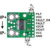
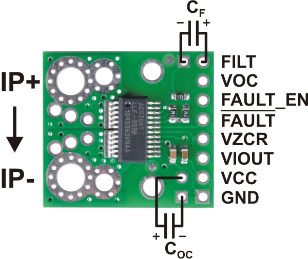
The pads are labeled on the bottom silkscreen, as shown in the picture above. The silkscreen also shows the direction that is interpreted as positive current flow via the +i arrow.
Note: The sensor’s extended -75 A to 75 A range should be limited to transient currents. In Pololu's tests, Pololu found that the IC could tolerate 50 A for 20 seconds or 37.5 A for 150 seconds before exceeding its maximum temperature rating of 150°C. Therefore, unless you are taking special steps to keep the IC cool, Pololu recommend limiting continuous currents to under 30 A. Even with a low conductive path resistance of 1.1 mO, the board can get hot enough to burn you when the current is in the tens of amps, and the IC does not feature any kind of over-temperature protection, so thermal issues should be taken into consideration for high currents.
 |
Using the sensor
Electrical connections
The only connections required to use this sensor are the input current (IP+ and IP-), logic power (VCC and GND), and the sensor output (VIOUT). All of the other pins are optional, as are the two external capacitors shown in the diagram to the right.
The sensor requires a supply voltage of 3 V to 5.5 V to be connected across the VCC and GND pads, which are labeled on the bottom silkscreen. The sensor outputs an analog voltage that is linearly proportional to the input current. The quiescent output voltage is VCC/2 and changes by 28 mV per amp of input current (when VCC = 5 V), with positive current increasing the output voltage and negative current decreasing the output voltage. For an arbitrary input current i (in amps), the sensor’s output voltage can be more generally represented as:
VIOUT = (0.028 V/A * i + 2.5 V) * VCC / 5 V
The VZCR pin is the voltage reference output pin and can be used as a zero current (0 A) reference. It will be approximately equal to VCC/2 and lets you more accurately compute the current from the VIOUT output voltage.
The FILT pin lets you adjust the board’s bandwidth by adding a capacitor, CF, to ground (a ground pad has been added next to the FILT pin for convenience). Without any external filter capacitor, the bandwidth is 120 kHz. The datasheet provides more information on how the external filter capacitor affects bandwidth.
The FAULT pin is normally high and latches low when the current exceeds the overcurrent fault switchpoint (Ioc). This switchpoint is set by the voltage applied to the VOC pin and is dependent on the voltage divider shown in the schematic diagram below. By default, Ioc is set to 57 A, but it can be altered by adding external resistors to the voltage divider to change the VOC voltage. Once the FAULT pin is latched low, it can be reset by driving the FAULT_EN input low (this input is pulled high on the board). An external capacitor, COC, can be added to increase the overcurrent fault response time. Without this capacitor, the fault response time is typically under 2 µs. For detailed information on using the overcurrent fault feature, including some key restrictions on the overcurrent threshold, please refer to the ACS709 datasheet (1MB pdf).
|
|
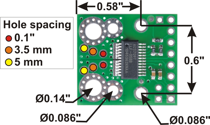
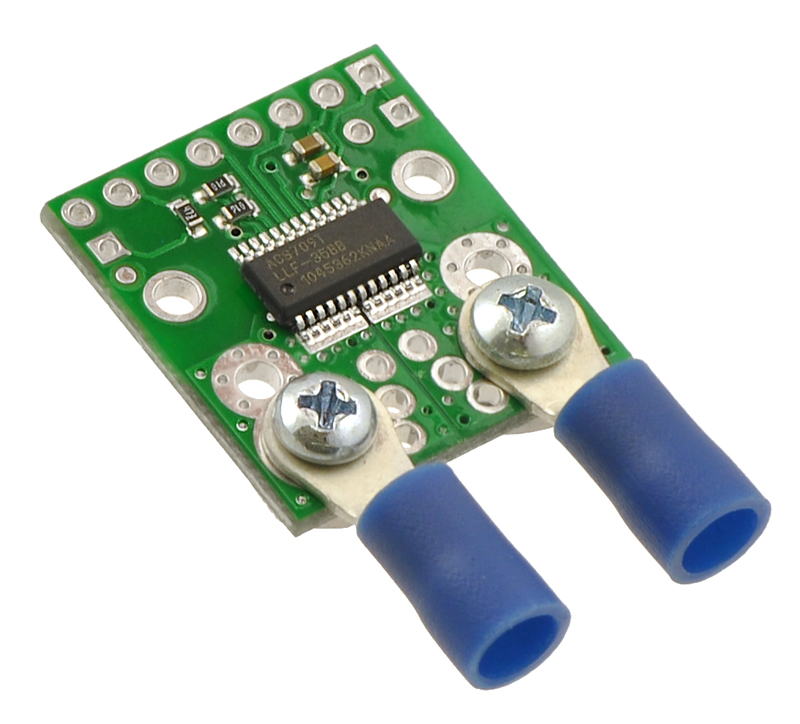
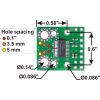
The input current can be connected to the board in a variety of ways. Holes with 0.1", 3.5 mm, and 5 mm spacing are available as shown in the diagram above for connecting male header pins or terminal blocks. For high-current applications, you can solder wires directly to the through-holes that best match your wires, or you can use solderless ring terminal connectors, as shown in the picture above. The large through-holes are big enough for #6 screws.
Warning: This product is intended for use below 30 V. Working with higher voltages can be extremely dangerous and should only be attempted by qualified individuals with appropriate equipment and protective gear.
Mounting information
The board has two mounting holes on the logic side of the board. These mounting holes are 0.6" apart and are designed for #2 screws.
Included components
This board ships assembled with all surface mount components, and an 8×1 strip of 0.1" header pins is included but not soldered in, as shown in the picture below.
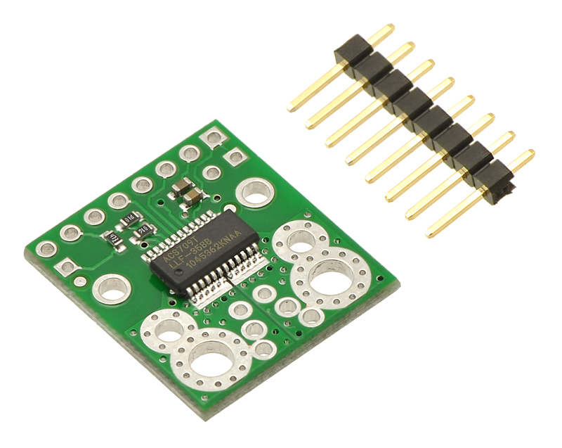 |
ACS709 current sensor carrier with included 8 × 1 0.1" header pins. |
|---|
Schematic diagram
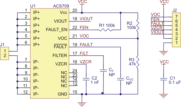 |
ACS709 current sensor carrier schematic diagram. |
|---|
People often buy this product together with:
 | ACS714 Current Sensor Carrier -5A to +5A |
 | ACS711EX Current Sensor Carrier -31A to +31A |
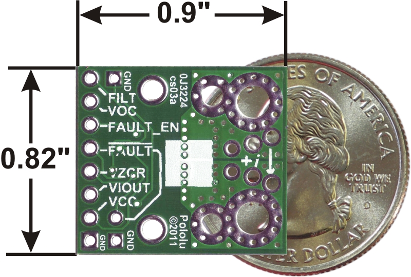
Dimensions
| Size: | 0.82" x 0.9" |
|---|---|
| Weight: | 1.7 g1 |
General specifications
| Current sense: | 0.018 V/A2 |
|---|---|
| Minimum logic voltage: | 3 V |
| Maximum logic voltage: | 5.5 V |
| Supply current: | 11 mA |
Notes:
- 1
- Without included optional header pins.
- 2
- When Vcc is 3.3 V. This specification is proportional to Vcc.
File downloads
-
Allegro ACS709 current sensor datasheet (1MB pdf)
Exact shipping can be calculated on the view cart page (no login required).
Products that weigh more than 0.5 KG may cost more than what's shown (for example, test equipment, machines, >500mL liquids, etc).
We deliver Australia-wide with these options (depends on the final destination - you can get a quote on the view cart page):
- $3+ for Stamped Mail (typically 10+ business days, not tracked, only available on selected small items)
- $6+ for Standard Post (typically 6+ business days, tracked)
- $10+ for Express Post (typically 2+ business days, tracked)
- Pickup - Free! Only available to customers who live in the Newcastle region (must order online and only pickup after we email to notify you the order is ready). Orders placed after 2PM may not be ready until the following business day.
Non-metro addresses in WA, NT, SA & TAS can take 2+ days in addition to the above information.
Some batteries (such as LiPo) can't be shipped by Air. During checkout, Express Post and International Methods will not be an option if you have that type of battery in your shopping cart.
International Orders - the following rates are for New Zealand and will vary for other countries:
- $11+ for Pack and Track (3+ days, tracked)
- $16+ for Express International (2-5 days, tracked)
If you order lots of gear, the postage amount will increase based on the weight of your order.
Our physical address (here's a PDF which includes other key business details):
Unit 18, 132 Garden Grove Parade
Adamstown
NSW, 2289
Australia
Take a look at our customer service page if you have other questions such as "do we do purchase orders" (yes!) or "are prices GST inclusive" (yes they are!). We're here to help - get in touch with us to talk shop.
Have a product question? We're here to help!
Videos
View AllGuides

The Maker Revolution

Getting Hands-on with Sensors
Projects

WhyzaGC - Feather ESP32 addon to the MightyOhm Gieger Counter

Makers love reviews as much as you do, please follow this link to review the products you have purchased.
Product Comments